
Diaphragm spraying production line

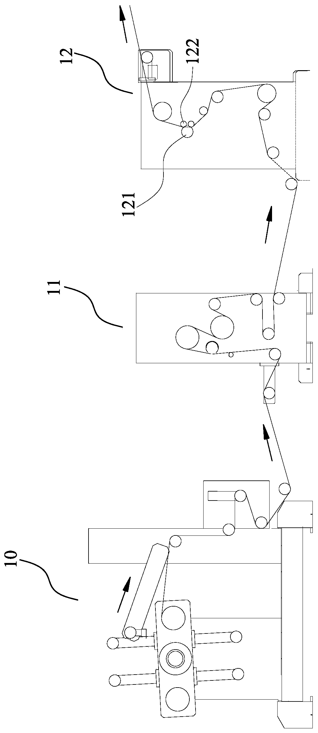
A technology of production line and diaphragm, which is applied in the direction of coating, spray booth, spraying device, etc., can solve the problems of slurry waste, affecting the uniformity of diaphragm, and water drop defects of diaphragm, so as to avoid water drop defects, avoid free distribution, improve average and degree effect

Pending Publication Date: 2020-07-17
JIANGSU ADVANCED MATERIAL TECH CO LTD
View PDF0 Cites 1 Cited by
  • Summary
  • Abstract
  • Description
  • Claims
  • Application Information

AI Technical Summary

Problems solved by technology

This way of moving the belt will cause the mist slurry to be driven upward by the movement of the diaphragm. If a material receiving device is installed above the sprayer, the mist slurry will condense on the surface of the material receiving device and drop to the surface of the diaphragm, resulting in water drop defects on the diaphragm , which affects the excellent rate of diaphragm spraying products; at the same time, the mist-like slurry diverges freely after going up, causing environmental pollution in the workshop, personnel health threats and waste of slurry; Inversion, but using an inversion frame will affect the flatness of the diaphragm, which in turn will affect the uniformity of the diaphragm

Method used


Image

  • Diaphragm spraying production line
  • Diaphragm spraying production line
  • Diaphragm spraying production line

Examples


Embodiment Construction

[0030] In the description of the present invention, it should be noted that the terms "center", "upper", "lower", "left", "right", "vertical", "horizontal", "inner", "outer" etc. The indicated orientation or positional relationship is based on the orientation or positional relationship shown in the drawings, and is only for the convenience of describing the invention and simplifying the description, rather than indicating or implying that the indicated position or element must have a specific orientation or be constructed in a specific orientation. and operation, and therefore should not be construed as limiting the invention.

[0031] In the description of the present invention, it should be noted that unless otherwise specified and limited, the terms "installation", "connection" and "connection" should be understood in a broad sense, for example, it can be a fixed connection or a detachable connection. Connected, or integrally connected; it may be mechanically connected or e...


PUM


Abstract

The invention provides a diaphragm spraying production line. The diaphragm spraying production line comprises an unwinding mechanism, a coating mechanism, a drying oven and a winding mechanism; the coating mechanism comprises a roller coating mechanism and a spraying mechanism which are used for coating the same side of a diaphragm with slurry, the unwinding mechanism and the winding mechanism arearranged on the same side of the drying oven, the roller coating mechanism and the spraying mechanism are arranged on the two sides of the drying oven correspondingly, and the roller coating mechanism is arranged between the unwinding mechanism and the drying oven; the spraying mechanism comprises a spraying device and spraying guide rollers used for unfolding the diaphragm, the spraying guide rollers comprise the upper guide roller and the lower guide roller, and a material receiving groove used for recycling vaporous slurry is formed below the spraying device; and the diaphragm is unwound from the unwinding mechanism and sequentially passes through the roller coating mechanism, the drying oven, the side, facing the spraying device, of the upper guide roller, the side, facing the spraying device, of the lower guide roller and the drying oven to reach the winding mechanism. According to the diaphragm spraying production line, the vaporific slurry can be prevented from condensing and dropping onto the surface of the diaphragm, the vaporific slurry can be recycled, and the same surface of the diaphragm can be coated without additionally arranging an overturning frame.

Description

technical field [0001] The invention relates to the technical field of diaphragm production equipment, in particular to a diaphragm spraying production line. Background technique [0002] The spraying process is widely used in the coating of flexible diaphragms. The design of the existing diaphragm spraying production line is as follows: figure 1 As shown, the diaphragm passes through one side of the output end of the spraying device from bottom to top, so that the mist slurry adheres to the surface of the diaphragm. This way of moving the belt will cause the mist slurry to be driven upward by the movement of the diaphragm. If a material receiving device is installed above the sprayer, the mist slurry will condense on the surface of the material receiving device and drop to the surface of the diaphragm, resulting in water drop-shaped defects on the diaphragm , which affects the excellent rate of diaphragm spraying products; at the same time, the mist-like slurry diverges fr...

Claims


Application Information

Patent Timeline
Patent Type & Authority Applications(China)
IPC IPC(8): B05C9/14B05C1/08B05C13/02B05B13/02B05B14/40B05B16/20
CPCB05C9/14B05C1/083B05C13/02B05B13/0221B05B14/40B05B16/20Y02P70/10
Inventor 孙东岳王晓明黄士斌徐强包慧
Owner JIANGSU ADVANCED MATERIAL TECH CO LTD
Learn More