
Ventilated moisture-proof power cabinet

A technology for power cabinets and ventilation devices, applied in the field of electric power, which can solve the problems of power consumption, high manufacturing costs, and increased hazards in the use of transformer boxes, and achieve the effects of avoiding energy loss and low manufacturing costs

Inactive Publication Date: 2020-11-27
包丽丽
View PDF1 Cites 0 Cited by
  • Summary
  • Abstract
  • Description
  • Claims
  • Application Information

AI Technical Summary

Problems solved by technology

[0002] At present, with the rapid development of electric power technology, outdoor transformer boxes, power distribution cabinets and other cabinets for the installation of various electrical components have also been fully developed. However, after the installation of the transformer box is completed, regular or Unscheduled maintenance and inspection, this is to prevent accidents caused by aging or short circuit of the electrical components inside the transformer box, and reduce the loss of public property, but the electrical components inside the transformer box will generate a large amount of Especially in summer, due to the narrow space inside the transformer box, it is not only not conducive to the construction personnel to repair and deal with the inside of the transformer box, but also makes it difficult for the heat inside the transformer box to dissipate into the air, which is easy to The electrical components inside the transformer box will be damaged due to high temperature, or the circuit connection wires will be short-circuited due to high temperature, which will greatly increase the hazards of using conventional transformer boxes, and the humid environment will cause corrosion of power cabinets or metal devices, shortening service life, for this reason, we propose a power cabinet dehumidification device
[0003] After retrieval, the Chinese Patent No. CN108988167A discloses a power cabinet dehumidification device, including a power cabinet, the upper end of the power cabinet is provided with a breathable cabin, and the lower end of the power cabinet is heated by a grid plate It is fixedly connected with the base, the inner cavity of the base is provided with more than two motors, the output end of the motor is fixedly connected with the first fan, and the inside of the power cabinet is provided with a drying chamber in the circumferential direction, and the inner cavity of the drying chamber Filled with silica gel, the top plate of the power cabinet is provided with more than two fixing devices, the fixing device is provided with a second fan, the top of the breathable cabin is provided with a top cover, and the edge of the top cover is fixedly connected to the rain The side wall of the air-permeable cabin is provided with more than two filter screens. The power cabinet dehumidification device has a fast dehumidification speed and a good dehumidification effect, prolonging the service life of the power cabinet and power components, making the use of the power cabinet safer, but The device uses the motor to dehumidify the power cabinet, which requires power consumption and high cost of use. At the same time, due to the use of the motor, the manufacturing cost is also high, which is not conducive to large-scale promotion

Method used


Image

  • Ventilated moisture-proof power cabinet
  • Ventilated moisture-proof power cabinet
  • Ventilated moisture-proof power cabinet

Examples


Embodiment 1

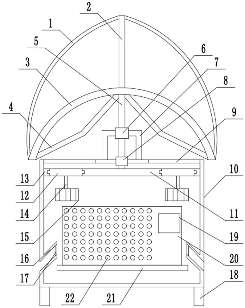
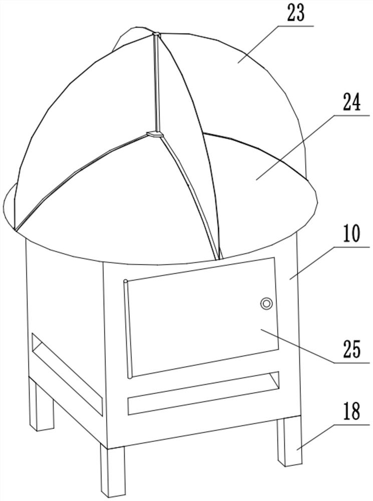
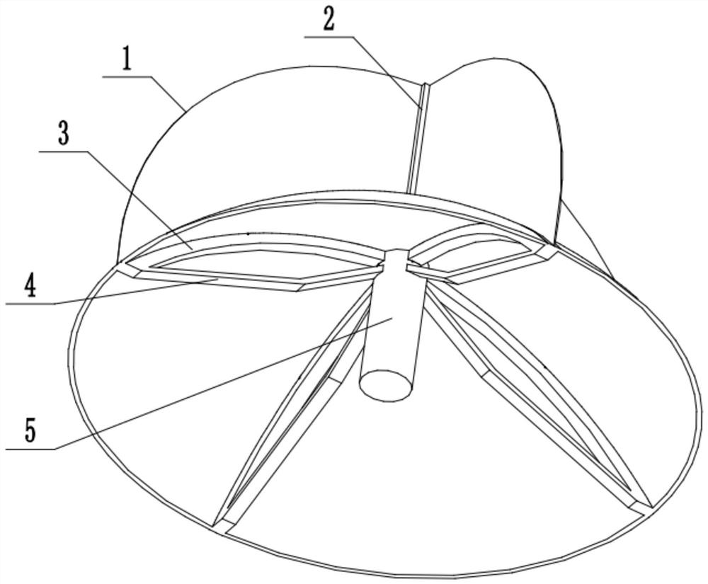
[0026] See Figure 1~3 In the embodiment of the present invention, a ventilated and moisture-proof power cabinet includes a rack 10, an air inlet 16 is installed on the outside of the rack 10 for the entry of outside air, and a second bearing 8 is installed at the upper middle of the rack 10, Used to install the rotating shaft 5, the middle of the second bearing 8 is installed with a rotating shaft 5, used to install the upper second bending rod 3, the upper part of the rotating shaft 5 is installed with at least three second bending rods 3, used to install rain film 24. A rain-shielding film 24 is covered between the second curved rods 3 to block rainwater when it rains. A support rod 2 is installed at the upper end of the rotating shaft 5 for installing the first curved rod 1, and the upper end of the support rod 2 is installed There are at least three first bending rods 1 for installing a wind-bearing film 23, and the first bending rods 1 are covered with a wind-bearing film...

Embodiment 2

[0031] See Figure 1~3 In an embodiment of the present invention, a ventilated and moisture-proof power cabinet includes a rack 10, an air inlet 16 is installed on the outside of the rack 10 for the entry of outside air, and a second bearing 8 is installed at the upper middle of the rack 10, Used to install the rotating shaft 5, the middle of the second bearing 8 is installed with the rotating shaft 5, used to install the upper second bending rod 3, the upper part of the rotating shaft 5 is installed with at least three second bending rods 3, used to install the rain film 24. There is a rain-shielding film 24 between the second bending rods 3, which is used to block rainwater when it rains. The upper end of the rotating shaft 5 is equipped with a support rod 2 for installing the first bending rod 1, and the upper end of the support rod 2 is installed There are at least three first bending rods 1 for installing a wind-bearing film 23, and the first bending rods 1 are covered wit...


PUM


Abstract

The invention relates to the field of power and relates to a power cabinet including a machine frame, wherein an air inlet is formed in the outer side of the rack; a second bearing is mounted in the middle of the upper end of the rack; a rotating shaft is mounted in the middle of the second bearing; at least three second bent rods are mounted at the upper part of the rotating shaft; a rain shielding film is covered between the second bent rods; a supporting rod is mounted at the upper end of the rotating shaft; at least three first bent rods are installed at the upper end of the supporting rod. A wind bearing film is covered between the first bent rods; a ventilation device is mounted at the lower end of the rotating shaft; a placing device is mounted in the rack; through the arrangement of a rotating shaft, a second bent rod, a rain shielding film, a first bent rod, an air bearing film and a ventilation device, air in the rack drives the air bearing film to rotate through natural wind; the wind bearing film drives the rotating rod to rotate, and the rotating rod drives the ventilation device through the driving gear; so that air is circulated, water vapor is prevented from condensing and dripping on electrical apparatus elements due to humid and unventilated weather, and large-area popularization is facilitated.

Description

Technical field [0001] The invention relates to the field of electric power, in particular to a ventilation and moisture-proof electric cabinet. Background technique [0002] At present, with the rapid development of power technology, outdoor transformer boxes, power distribution cabinets and other cabinets used to meet the installation of various electrical components have also been adequately developed. However, after the installation of transformer boxes, regular or Unscheduled maintenance and inspection are to prevent accidents caused by aging or short circuit of electrical components inside the substation, and to reduce the loss of public property. However, the electrical components inside the substation will produce a large amount of electricity during long-term operation. Especially in summer, due to the small space inside the transformer box, it is not only not conducive to the maintenance and treatment of the inside of the transformer box, but also makes it difficult for...

Claims


Application Information

Patent Timeline
Patent Type & Authority Applications(China)
IPC IPC(8): H02B1/56H02B1/30H02B1/28
CPCH02B1/28H02B1/30H02B1/565
Inventor 包丽丽
Owner 包丽丽
Learn More