
Gas distribution drying furnace

A drying furnace and gas distribution technology, applied in drying, drying machines, drying chambers/containers, etc., can solve the problems of high power, short service life, high cost, etc., achieve long service life, low cost, and prevent condensation dripping effect

Inactive Publication Date: 2012-08-08
张家港鹏博光电科技有限公司
View PDF7 Cites 0 Cited by
  • Summary
  • Abstract
  • Description
  • Claims
  • Application Information

AI Technical Summary

Problems solved by technology

The drying furnace in the prior art has relatively high power, high cost, and short service life, and cannot deal with the influence of condensation and dripping of oily substances evaporated during the drying process on silicon wafers.

Method used


Image

  • Gas distribution drying furnace
  • Gas distribution drying furnace

Examples


Embodiment Construction

[0014] The preferred embodiments of the present invention will be described below in conjunction with the accompanying drawings. It should be understood that the preferred embodiments described here are only used to illustrate and explain the present invention, and are not intended to limit the present invention.

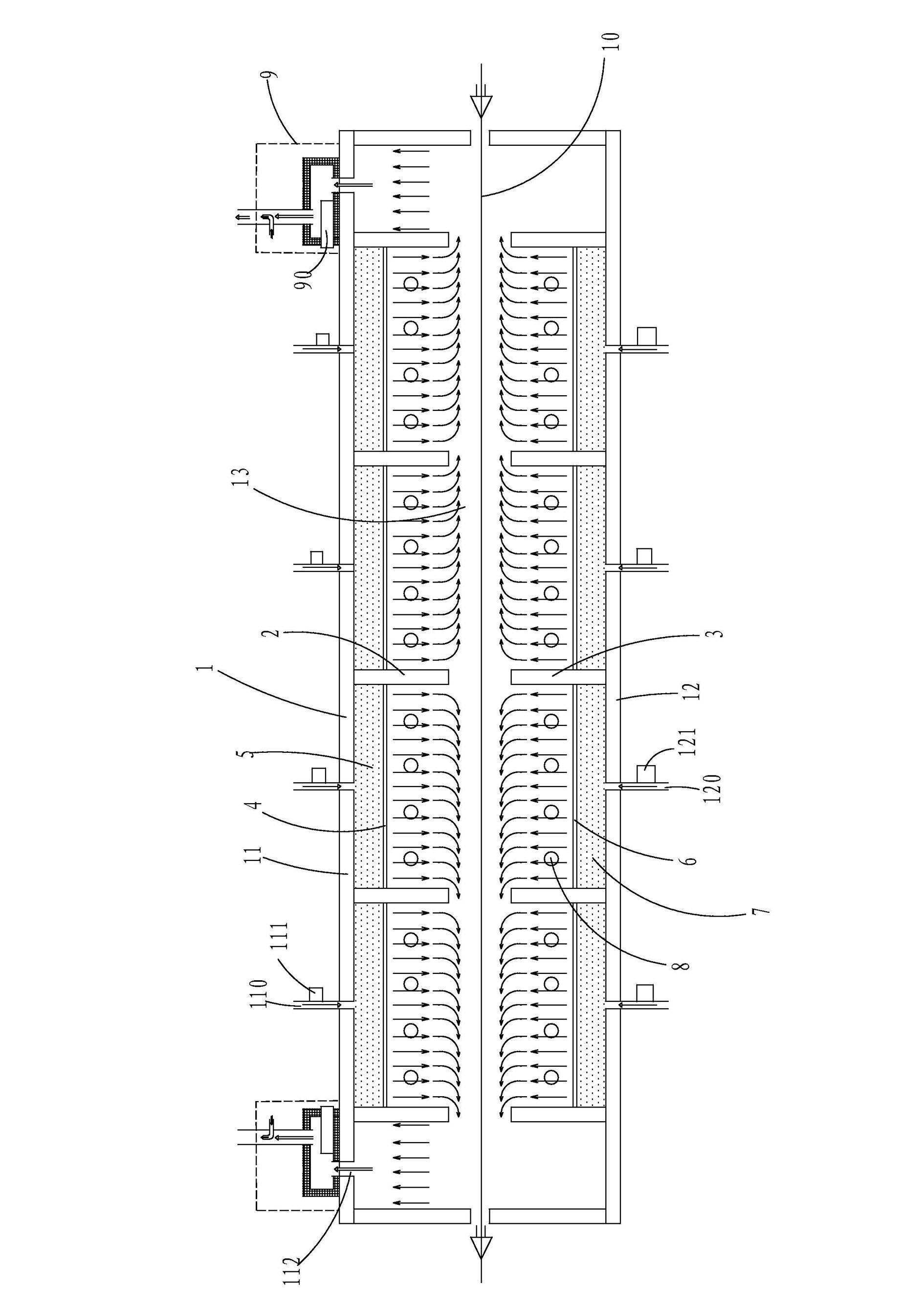
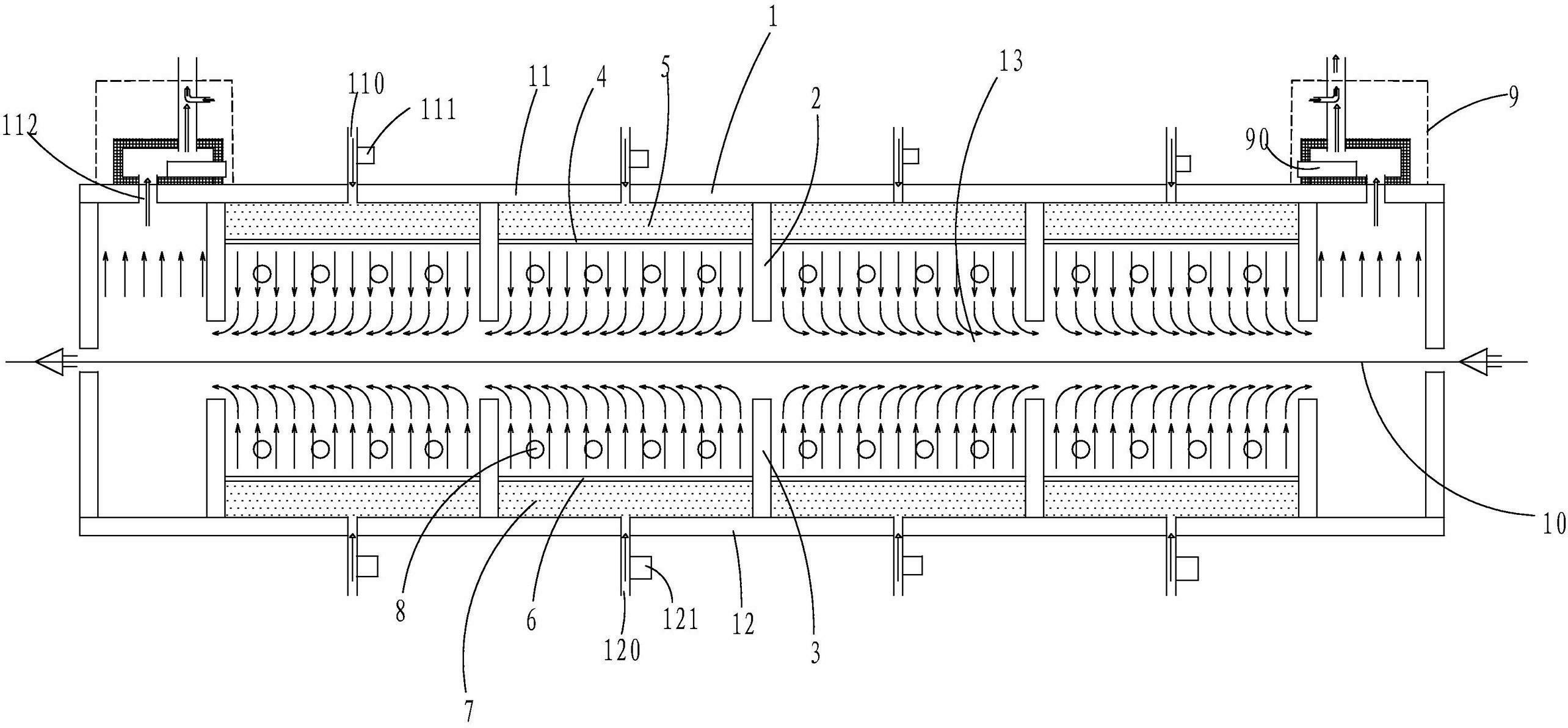
[0015] see figure 1 , a gas distribution drying furnace, comprising: a furnace body 1, the center of the furnace body 1 is provided with a drying channel 10, the furnace body 1 includes a top wall 11, a bottom wall 12, connected to the top wall 11 and the bottom wall The two end walls at both ends of the wall 12 and the two side walls connected to both sides of the top wall 11 and the bottom wall 12, the above-mentioned six walls surround and form a furnace chamber 13, and several groups of insulation partitions are arranged in the furnace chamber 13, and each group of insulation The partition includes a first thermal insulation partition 2 connected to the top wall...


PUM


Abstract

The invention discloses a gas distribution drying furnace, which comprises a furnace body and a furnace cavity, wherein the furnace body is provided with a drying passage, a plurality of groups of heat insulation plates are arranged in the furnace cavity, each group of the heat insulation plates comprises a first heat insulation plate and a second heat insulation plate, the first heat insulation plate is connected with the top wall, the second insulation separation plate is connected with the bottom wall, a first gas distribution plate is arranged between every two adjacent first heat insulation separation plates, the top wall is provided with a plurality of first gas inlet, one side of each first gas inlet is respectively provided with a first temperature control device, a second gas distribution plate is arranged between every two second heat insulation plates, the bottom wall is provided a plurality of second gas inlets, one side of each second gas inlet is respectively provided with a second temperature control device, a heating device is arranged on the side wall, two ends of the top wall are respectively provided with gas outlets, an exhausting device is arranged above each gas outlet, and oil storage grooves are arranged in the exhausting devices. The gas distribution drying furnace disclosed by the invention has the advantages that the structure is simple, the cost is lower, the service life is longer, and the constant temperature drying can be realized.

Description

technical field [0001] The invention relates to a drying furnace in the solar silicon wafer industry, in particular to a gas distribution drying furnace which regulates temperature through air flow. Background technique [0002] The drying of silicon wafers in the solar silicon wafer industry is a very important step in the entire production process of solar silicon wafers. The silicon wafer passes through a drying furnace channel at a certain temperature, so that the paste printed on both sides of the silicon wafer can remove water and other oily substances, so that useful materials can be evenly and firmly attached to the silicon wafer. Among them, the uniformity and stability control of the drying temperature during the drying process is very important. Whether the constant temperature drying can be guaranteed during the entire drying process has a great influence on the quality of the silicon wafer. Moreover, oily substances such as water vapor produced during the dryin...

Claims


Application Information

Patent Timeline
Patent Type & Authority Applications(China)
IPC IPC(8): F26B21/00F26B21/10F26B25/08
Inventor 张辉
Owner 张家港鹏博光电科技有限公司
Learn More