Nozzle plate for fuel injection device

A fuel injection device and a fuel injection technology are applied in the directions of the fuel injection device, the charging system, the engine components, etc., which can solve the problems such as the inability to determine the advancing direction of the spray 105, the inability to change the advancing direction of the spray 105, etc., so as to improve the fuel consumption efficiency. Effect

Inactive Publication Date: 2016-10-12
ENPLAS
View PDF5 Cites 0 Cited by
  • Summary
  • Abstract
  • Description
  • Claims
  • Application Information

AI Technical Summary

Problems solved by technology

[0009] but, Figure 14 Although the shown fuel injection device 100 limits the range of the spray 105, it cannot change the advancing direction of the spray 105. Therefore, the advancing direction of the spray 105 cannot be determined according to the shape of the intake pipe 103, and the particles of fuel in the spray 105 adhere to Problems with the wall surface other than the wall surface of the branch portion 106 of the intake pipe 103

Method used


Image

  • Nozzle plate for fuel injection device
  • Nozzle plate for fuel injection device
  • Nozzle plate for fuel injection device

Examples


no. 1 approach

[0031] (Use status of fuel injection device)

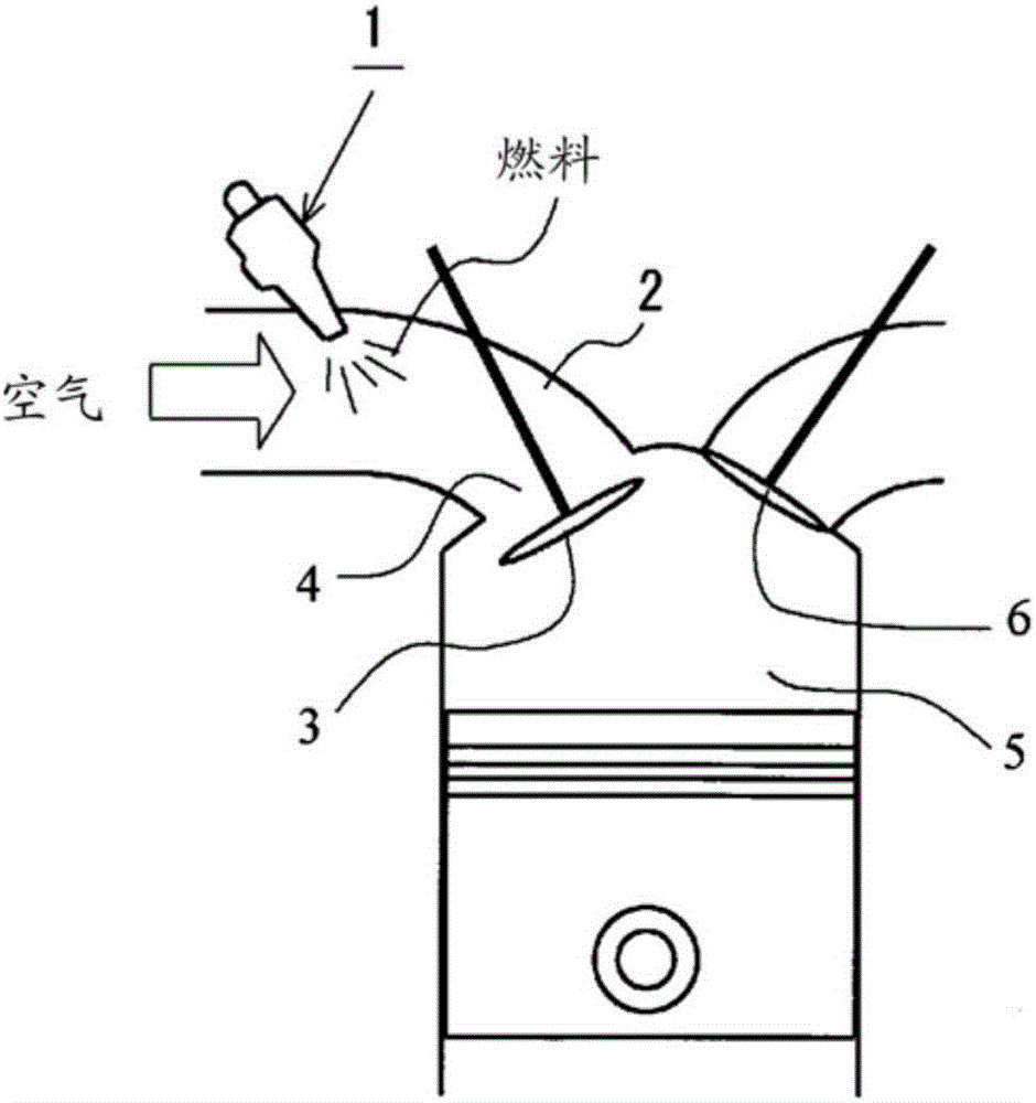
[0032] figure 1 It is a figure which schematically shows the usage state of the fuel injection apparatus 1 to which the nozzle plate for fuel injection apparatuses of this embodiment is attached. as it should figure 1 As shown, the fuel injection device 1 of the port injection method is installed in the middle of the intake pipe 2 of the 4-valve engine. Fuel is injected into the air pipe 2 to mix the air introduced into the intake pipe 2 with the fuel, and the combustible mixture is supplied from the intake port 4 into the cylinder 5 . also, figure 1 Only one of the two intake valves 3 and one of the two exhaust valves (exhaust valves) 6 is shown.

[0033] (Schematic structure of fuel injection device)

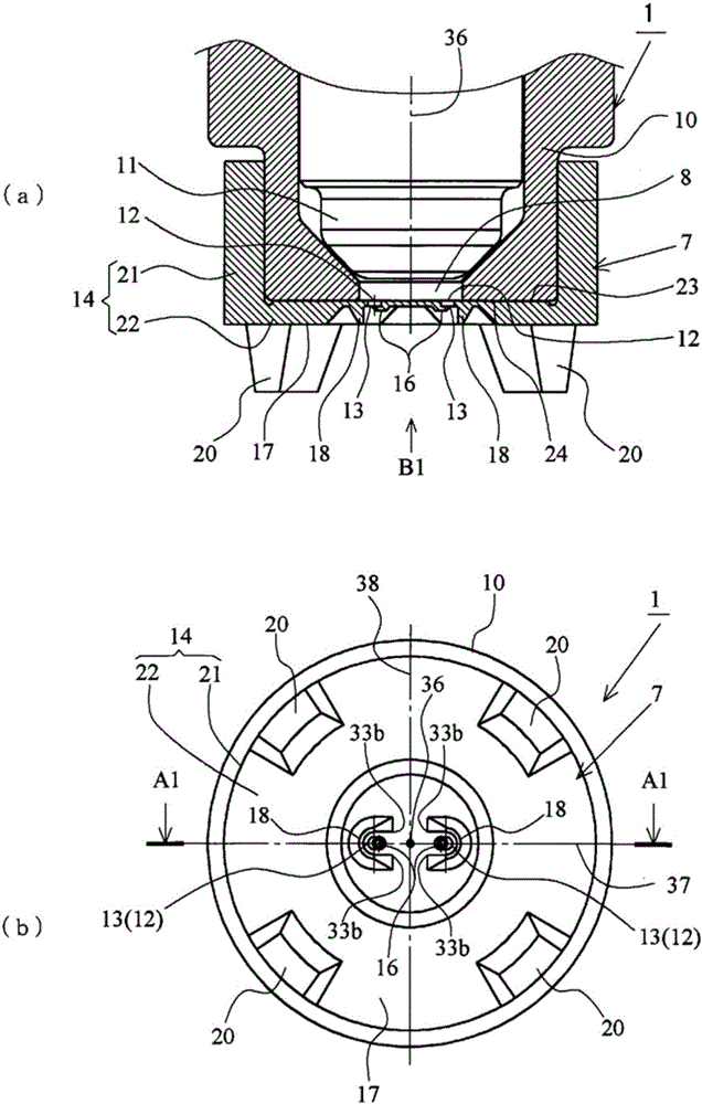
[0034] figure 2 It is a figure which shows the front-end side of the fuel injection apparatus 1 to which the nozzle plate 7 for fuel injection apparatuses (hereinafter referred to as a nozzle plate) is attached. also, f...

no. 2 approach

[0053] Image 6 It is a figure which shows a part of the nozzle plate 7 of 2nd Embodiment of this invention, and is a figure which shows the 1st modification of the nozzle plate 7 of 1st Embodiment. In addition, in the nozzle plate 7 of the present embodiment, the same reference numerals are attached to the same parts as those of the nozzle plate 7 of the first embodiment, and descriptions that overlap with those of the nozzle plate 7 of the first embodiment are omitted.

[0054] The nozzle plate 7 of the present embodiment is formed in such a manner that the inner wall surface 31 of the spray direction changing device 18 becomes an inclined surface, and the inner wall surface 31 faces the normal direction ( Image 6 (b) + Z axis direction) open.

[0055] The nozzle plate 7 of this embodiment can make the spray sprayed from the orifice 13 collide with the inner wall surface 31 of the spray direction changing device 18, and the advancing direction of the spray colliding with t...

no. 3 approach

[0057] Figure 7 It is a figure which shows a part of the nozzle plate 7 of 3rd Embodiment of this invention, and is a figure which shows the 2nd modification of the nozzle plate 7 of 1st Embodiment. In addition, in the nozzle plate 7 of the present embodiment, the same reference numerals are attached to the same parts as those of the nozzle plate 7 of the first embodiment, and descriptions that overlap with those of the nozzle plate 7 of the first embodiment are omitted.

[0058] In the nozzle plate 7 of the present embodiment, when the bottom wall portion 22 (thin wall portion 22a) is viewed from the front side (in a planar view), the first inner wall surface portion 32 of the spray direction changing device 18 is formed to interfere with the The semicircle concentric with the center 16 a of 16 is a semicircle eccentric with respect to the center 12 a of the nozzle hole 12 . Such as Figure 7 As shown in (a), the first inner wall surface 32 is closest to the outlet 15 of t...


PUM


Abstract

To provide a nozzle plate for a fuel injection device, the nozzle plate being configured so that the direction of movement of spray can be determined according to the shape of an intake pipe, the position of an intake port, and other factors, thereby reducing the amount of fine fuel particles adhering to the branch section of the intake pipe, the wall surface of the intake pipe, and other portions. A nozzle plate (7), which is mounted at the fuel injection opening of a fuel injection device, has a nozzle hole (12) provided in the nozzle plate body (14), the nozzle hole (12) allowing fuel injected from the fuel injection opening to pass therethrough. A spray direction change means (18), against which fuel spray injected from the nozzle hole (12) strikes and which changes the direction of movement of the fuel spray, is provided integrally to the nozzle plate body (14) at a position on the outlet (15) side of the nozzle hole (12). Consequently, the direction of movement of the spray can be determined by the spray direction change means according to the shape of the intake pipe, the position of the intake port, and other factors.

Description

technical field [0001] The present invention relates to a nozzle plate for a fuel injection device that is attached to a fuel injection port of a fuel injection device to atomize and inject fuel flowing out of the fuel injection port. Background technique [0002] Internal combustion engines such as automobiles (hereinafter simply referred to as "engines") mix fuel injected from a fuel injection device with air introduced through an intake pipe to form a combustible mixture, and combust the combustible mixture in a cylinder. For this type of engine, it is known that the mixing state of fuel injected from the fuel injection device and air has a great influence on the performance of the engine. In particular, it is known that the atomization of the fuel injected from the fuel injection device is a factor affecting the performance of the engine. Important factor. Therefore, a nozzle plate for a fuel injection device (hereinafter, abbreviated as "nozzle plate" as appropriate) f...

Claims


Application Information

Patent Timeline
IPC IPC(8): F02M61/18
CPCF02M61/1853F02M61/1826F02M61/184
Inventor 野口幸二
Owner ENPLAS
Why Eureka
Try Eureka