Power generation system for ships

A technology for power generation systems and ships, applied in ship propulsion, control systems, control generators, etc., can solve problems such as deterioration of fuel consumption efficiency

Active Publication Date: 2020-08-11
MITSUBISHI SHIPBUILDING CO LTD
View PDF6 Cites 0 Cited by
  • Summary
  • Abstract
  • Description
  • Claims
  • Application Information

AI Technical Summary

Problems solved by technology

However, since the rated power of the generator is set according to the required power at the time of entering and leaving the port, during normal navigation, t...

Method used


Image

  • Power generation system for ships
  • Power generation system for ships
  • Power generation system for ships

Examples


Embodiment Construction

[0044] Hereinafter, preferred embodiments of the ship power generation system according to the present invention will be described in detail with reference to the drawings. In addition, this invention is not limited by this embodiment, When there exists several embodiment, the aspect which combined each embodiment is also included.

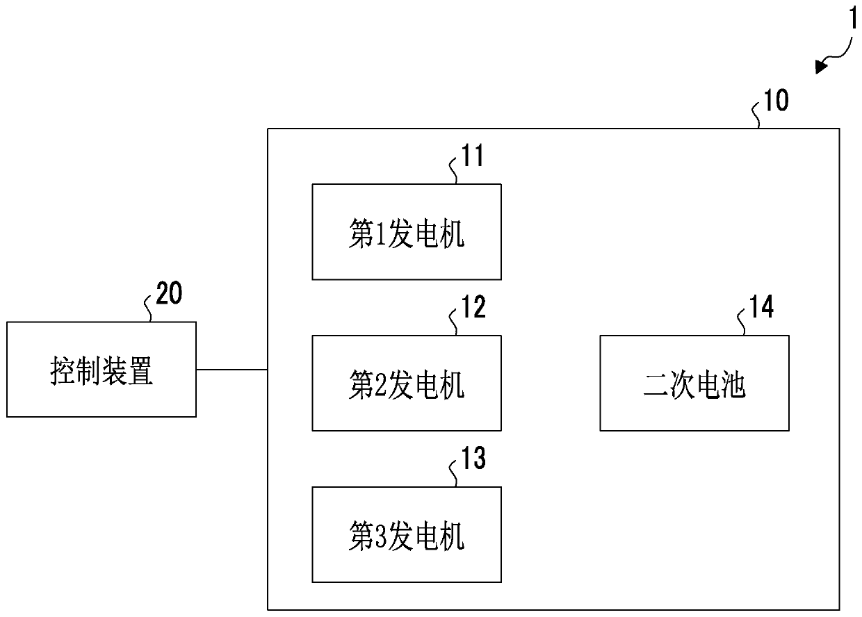
[0045] use figure 1 The configuration of the power generation system according to the first embodiment of the present invention will be described. figure 1 It is a block diagram showing the configuration of the power generation system according to the first embodiment of the present invention.

[0046] Such as figure 1 As shown, the power generation system 1 includes a main generator 10 and a control device 20 . The main generator 10 has a first generator 11 , a second generator 12 , a third generator 13 , and a secondary battery 14 . In addition, although the power generation system 1 has three generators, this is an example and does not limi...


PUM


Abstract

This power generation system for ships comprises: a plurality of generators (11, 12, 13) that supply power to the interior of a ship; a secondary battery 14 which stores the power output from the plurality of generators (11, 12, 13) and supplies the stored power to the interior of the ship; and a control device 20 that supplies the power to the ship using the first generator 11 among the pluralityof generators (11, 12, 13) and the secondary battery 14 during normal operation of the ship. The control device 20 charges the secondary battery 14 so as to enable output of power equivalent to thatof the first generator 11 during inward/outward clearance of the ship.

Description

technical field [0001] The invention relates to a power generation system of a ship. Background technique [0002] In ships such as ferries, multiple (for example, three) generators are mounted in order to supply power to inboard equipment in consideration of redundancy or the maximum power required, and each generator is operated so that the running time becomes equal . For example, when entering and leaving a port, it is necessary to use the maximum power when using equipment such as propeller propellers. In this case, three generators are running at high load. On the other hand, during normal navigation, power is supplied to the inside of the ship by two generators and the remaining one is kept on standby. [0003] Generally, the generator is designed to have the best fuel consumption efficiency at the rated output, so there will be no problem in fuel consumption efficiency when entering and leaving the port. However, since the rated power of the generator is set acco...

Claims


Application Information

Patent Timeline
IPC IPC(8): B63J99/00H02P9/04B63J3/02
CPCH02P9/04B63J3/02B63H2021/202B63J2003/002H02J3/322H02J2310/42B63J3/04H02J7/34
Inventor 黑岩良太大和邦昭
Owner MITSUBISHI SHIPBUILDING CO LTD
Why Eureka
Try Eureka