Switching device

A switchgear, switch technology, applied in electrical switches, protection switches, emergency protection devices, etc., can solve problems such as personal injury and equipment damage

Active Publication Date: 2016-10-12
EATON IND (AUSTRIA) GMBH
View PDF8 Cites 0 Cited by
  • Summary
  • Abstract
  • Description
  • Claims
  • Application Information

AI Technical Summary

Problems solved by technology

In addition to causing complete failure of the switchgear,

Method used


Image

  • Switching device
  • Switching device
  • Switching device

Examples


Embodiment Construction

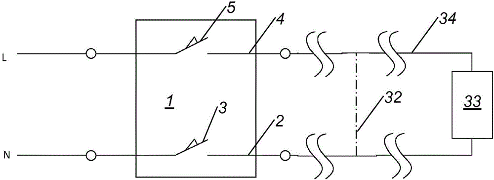
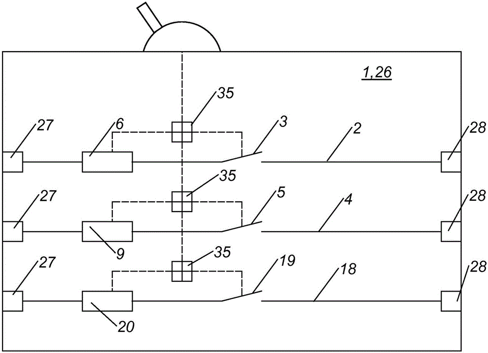
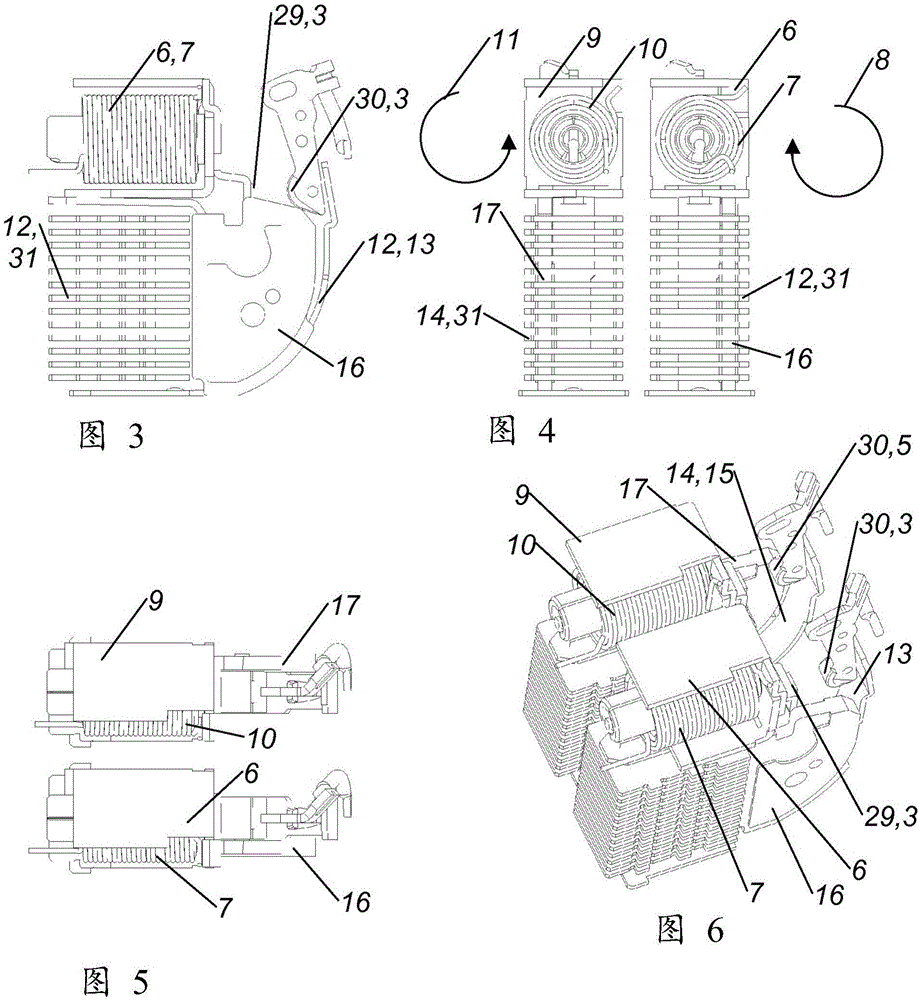
[0017] Figures 2 to 7 is one or more schematic diagrams of components of a preferred embodiment of a switching device 1 comprising a first switching path 2 with a first switching contact 3 and a second switching path 4 with a second switching contact 5, The first switching path 2 comprises a first electromagnetic trip device 6 with a first coil winding 7 having a first winding direction 8 and the second switching path 4 comprises a second electromagnetic tripping device 6 with a second coil winding 10 . Trip device 9, the second coil winding 10 has a second winding direction 11, the first switch contact 3 and the second switch contact 5 are coupled for substantially simultaneous actuation, and the first switch path 2 and the second The switching paths 4 are arranged side by side in the switching device 1 , wherein the first winding direction 8 is opposite to the second winding direction 11 .

[0018] As a result, it can be ensured that, due to tripping by means of one of the...


PUM


Abstract

The invention relates to a switching device (1) comprising a first switching path (2) having first switching contacts (3) and comprising a second switching path (4) having second switching contacts (5), wherein the first switching path (2) has a first electromagnetic tripping apparatus (6) having a first coil winding (7), wherein the first coil winding (7) has a first winding direction (8), wherein the second switching path (4) has a second electromagnetic tripping apparatus (9) having a second coil winding (10), wherein the second coil winding (10) has a second winding direction (11), wherein the first switching contacts (3) and the second switching contacts (5) are coupled for substantially simultaneous actuation, and wherein the first switching path (2) and the second switching path (4) are arranged adjacent to each other in the switching device (1), wherein, according to the invention, the first winding direction (8) is opposite the second winding direction (11).

Description

technical field [0001] The invention relates to a switching device according to the preamble of claim 1 . Background technique [0002] Switching devices are known which automatically open the switching contacts of the switching device when certain predetermined electrical conditions occur in the line passing through the switching device, and in this way interrupt the current flow in the line. This type of switching device is known as an automatic circuit breaker or circuit protection device. In order to detect a short circuit and to open the line rapidly in the event of a short circuit, electromagnetic tripping devices comprising a coil in which an armature is movably arranged are known and standard. In the event of a short circuit, a magnetic field is generated in the coil, which causes the armature to move, which in turn causes the switching contacts of the switching device concerned to open. [0003] When the current is interrupted, an arc is created between the switch...

Claims


Application Information

Patent Timeline
IPC IPC(8): H01H71/24
CPCH01H71/2409H01H71/2463H01H2071/249H01H33/10H01H33/38H01H71/24
Inventor M·卡岑施泰内尔
Owner EATON IND (AUSTRIA) GMBH
Why Eureka
Try Eureka