Power battery thermal management system with functions of efficient heat dissipation and efficient heating

A thermal management system and power battery technology, applied in the direction of batteries, secondary batteries, circuits, etc., can solve the problems of low temperature performance, failure to ensure temperature consistency between batteries, complex structure, etc., and achieve a simple overall structure The effect of stability, high machinability, and broad market prospects

Inactive Publication Date: 2016-10-19
广东万锦科技股份有限公司
View PDF5 Cites 36 Cited by
  • Summary
  • Abstract
  • Description
  • Claims
  • Application Information

AI Technical Summary

Benefits of technology

This patented technology describes an improved way to cool down batteries during their use without causing excess fluid (liquid) into other parts of the car's electrical systems. By incorporating this new type of materials called phase changes, these devices help keep the temperatures inside them even when they get too hot. Additionally, the device includes a special circuit board made up of two layers: one layer acts like a tank containing water while another layer helps distribute the heat generated through evaporation over time. Overall, this innovative design allows better control of the temperature of the entire battery package and improves safety measures against damage caused due to extreme conditions such as rapid increases in ambient air pressure.

Problems solved by technology

This patents describes various technical means for improving the efficiency and longevity (serviceability) of energy sources like lithium ion batteries due to their unique characteristics - they require efficient thermal management techniques while also being able to maintain proper temperatures within certain limits over long periods without losing functionality. Current solutions involve either air coolants or liquids coolant, each having its own limitations: gaseous leaks cause safety concerns; water evaporation causes corrosion damage on equipment and reduces lifespan; phase changes lead to poor charge/discharge capabilities and reduced lifetime. Additionally, current methods involving phase changing materials suffer from challenged operating conditions under extreme environments where condensations occur easily leading to failure.

Method used


Image

  • Power battery thermal management system with functions of efficient heat dissipation and efficient heating
  • Power battery thermal management system with functions of efficient heat dissipation and efficient heating
  • Power battery thermal management system with functions of efficient heat dissipation and efficient heating

Examples


specific Embodiment approach

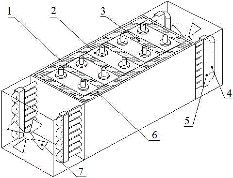
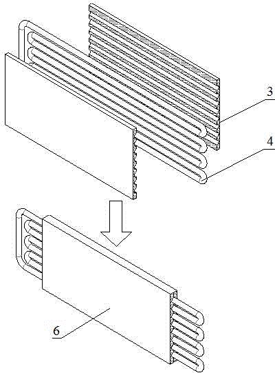
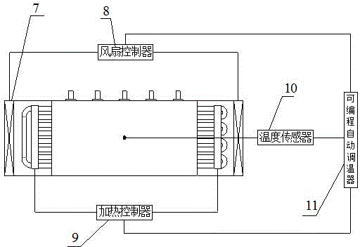
[0025] Specific embodiments: The power battery thermal management system with efficient heat dissipation and heating functions in this embodiment includes a power battery box and a thermal management control system; the power battery box includes a battery module shell 1, a battery cell 2, and a composite phase change material Plate 3, heat pipe 4, heating device 5, composite phase change material heat pipe coupling assembly 6, cooling fan 7. First, several battery cells 2 placed in the battery module casing are arranged adjacently to form a battery pack, and a composite phase-change material plate is sandwiched between two adjacent single cells and the outermost battery surface in the width direction of the battery pack 3. Composite phase-change material heat pipe coupling assemblies 6 are provided on both sides of the battery pack. The heat pipes of the composite phase-change material heat pipe coupling assemblies 6 protrude from the through holes on the battery module casing...


PUM


Abstract

The invention discloses a power battery thermal management system with functions of efficient heat dissipation and efficient heating. The power battery thermal management system comprises a power battery case and a thermal management system, wherein a plurality of battery monomers are adjacently aligned to form a battery pack placed inside a battery case housing, a composite phase change material plate is sandwiched between the gap of the adjacent batteries and the surface of the outermost side battery in the battery pack width direction, the composite phase change material plates and thermal pipes are combined to form composite phase change material thermal pipe coupling components, the composite phase change material thermal pipe coupling components are additionally arranged on both sides of the battery pack, the thermal pipes extends from the through holes on the battery module housing, the extending ends are connected to heating devices and heat dissipation fans, and a programmable automatic temperature regulator treats the signal from a temperature sensor by programming so as to determine whether the fans and the heating devices are started. The power battery thermal management system of the present invention has advantages of simple and firm whole structure, high efficiency, stable operating, and the like. In addition, the battery pack can be subjected to direct, unified and uniform cooling and heating, such that the battery can work at the appropriate temperature range, and the electric vehicle battery thermal management system is improved.

Description


Claims


Application Information

Patent Timeline
Owner 广东万锦科技股份有限公司
Why Eureka
Try Eureka