Multi-purpose mobile nursing rack

A mobile nursing and multi-functional technology, applied in the field of nursing racks, to achieve the effect of reducing pain, labor intensity and handling burden

Inactive Publication Date: 2016-10-26
王振琦 +2
View PDF15 Cites 3 Cited by
  • Summary
  • Abstract
  • Description
  • Claims
  • Application Information

AI Technical Summary

Problems solved by technology

[0004] The nursing racks in the prior art all use fixed brackets to change the position of the patient, and there is no specific setting of a highly reliable, portable, and multi-demand nursing rack for the aging problem.

Method used


Image

  • Multi-purpose mobile nursing rack
  • Multi-purpose mobile nursing rack
  • Multi-purpose mobile nursing rack

Examples


Embodiment 1

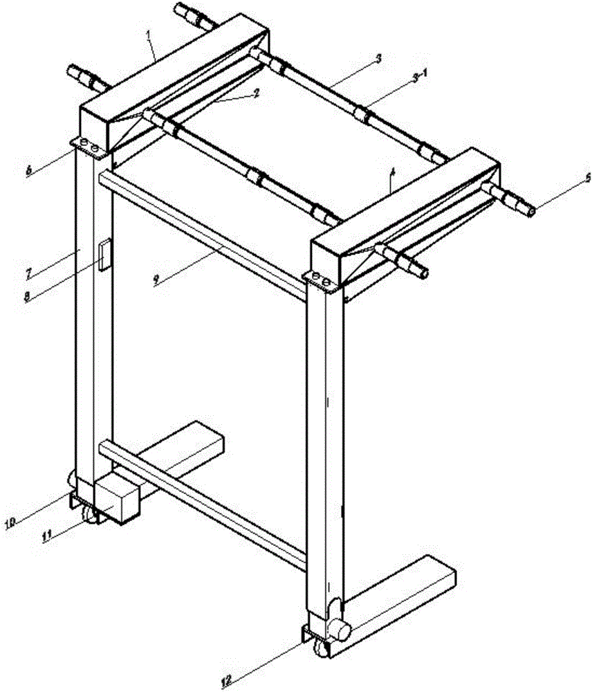
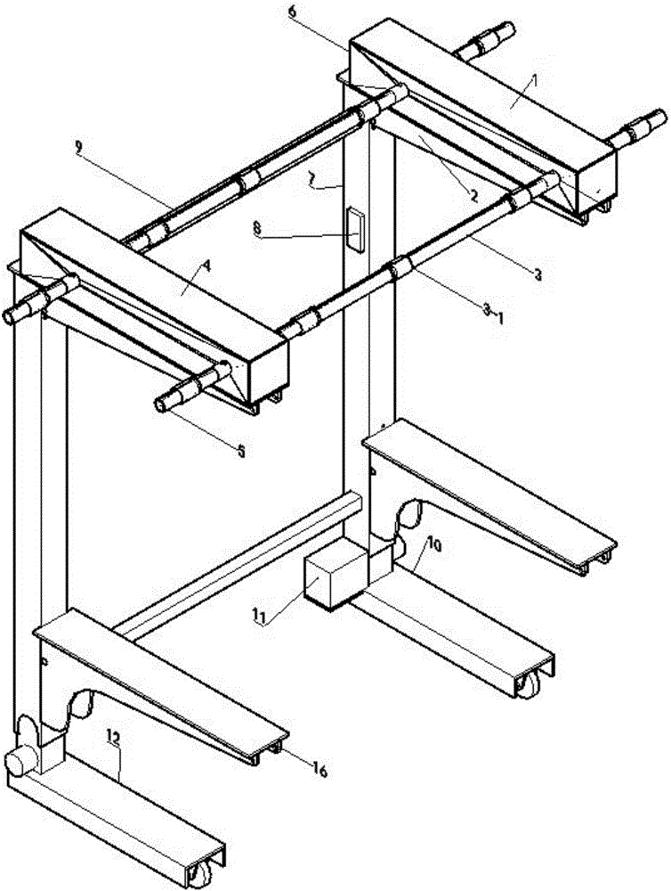
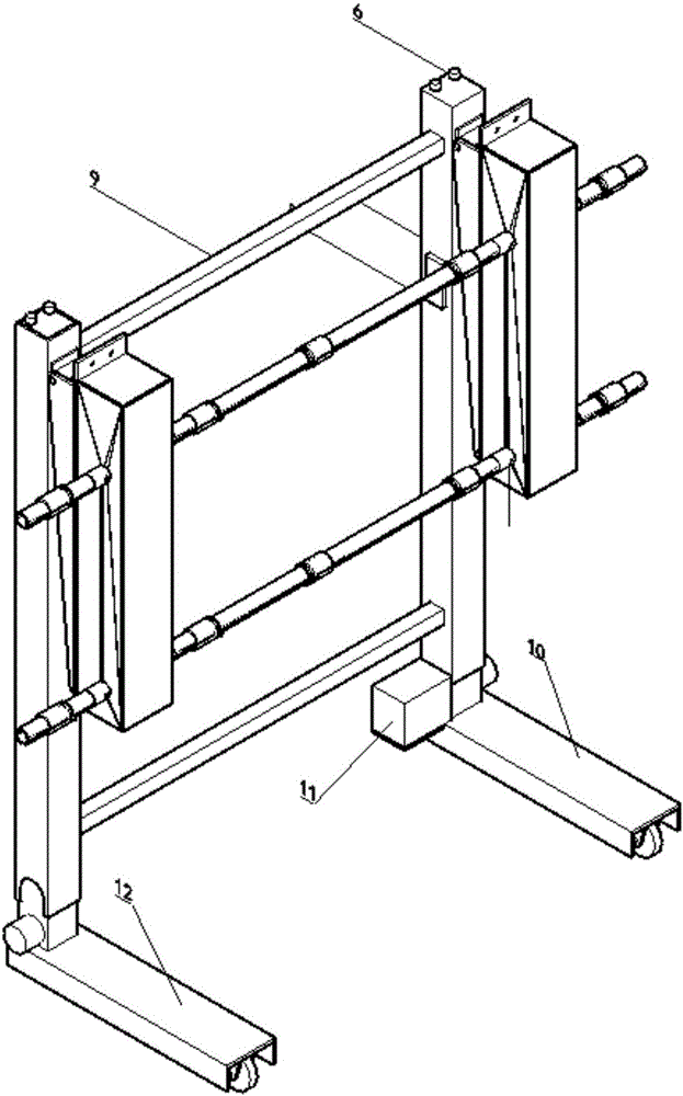
[0031] Embodiment 1: The multifunctional mobile nursing stand of the present invention includes a frame body composed of two support columns 7 and a fixed crossbeam 9 arranged between the two support columns 7, and a movable base is provided at the lower end of each support column 7 10 and 12, the bases 10 and 12 can be set in a contracted form and the power is provided by the battery pack 11, the top of each support column 7 is hinged with a support arm 2 and the support arm 2 and the support column 7 are fixedly connected by fastening bolts 6, A power box 1 and a driven box 4 are respectively arranged on the two support arms 2, and two hollow shafts 3 are installed between the power box 1 and the driven box 4, and a power box motor 20 is installed in the power box 1. Power box 1 is also provided with a force transmission mechanism with two opposite output ends, the input shaft of the force transmission mechanism is connected with the output end of the power box motor 20 throu...

Embodiment 2

[0032] Embodiment 2: Based on the above embodiments, the present invention can further be that: the force transmission mechanism is a worm gear transmission mechanism, a bevel gear transmission mechanism, or a rack and pinion transmission mechanism.

[0033] The worm gear transmission mechanism includes two oppositely rotating worms 22 and 27 installed on the input shaft, worm wheels 23 and 28 respectively installed on the two output shafts, and the two worms mesh with the corresponding worm wheels respectively;

[0034] The bevel gear transmission mechanism includes two No. 1 bevel gears with opposite rotation directions installed on the input shaft, and No. 2 bevel gears respectively installed on the two output shafts. The two No. 1 bevel gears are respectively connected to the corresponding No. 2 bevel gears. bevel gear meshing;

[0035] The rack-and-pinion transmission mechanism includes two racks with opposite rotation directions fixedly connected to the input shaft, gear...

Embodiment 3

[0036] Embodiment 3: Based on the above-mentioned embodiment, further the present invention can also be: the nursing facility is a hospital operating room and a body position lifting facility group designed by a special person or a soft bag body position lifting facility group or a sitting posture soft bag body position lifting facility group .

[0037] Such as Figure 4-Figure 6As shown: the body position lifting facility group designed by the operating room of the hospital and the special person includes a T-head 13-1 installed in a T-shaped slot structure, connected by a metal fixing sleeve 13-6 and a lock nut 13-7 The two hard pallets 13-4 and 13-9, the end of each T-shaped head is connected with a soft belt, and the end of each soft belt is connected to the corresponding hard belt through the soft belt fixed distance clip 13-3. pallet connection. T-shaped fastening head, fixed No. 13-2 soft belt, which plays the role of soft belt clamping. The soft belt fixed distance c...


PUM


Abstract

The invention provides a multi-purpose mobile nursing rack. The multi-purpose mobile nursing rack comprises a rack body composed of two support posts and a fixing cross beam arranged between the two support posts, wherein a support arm is hinged to the top of each support post, a power box and a driven box are arranged on the two support arms respectively, two hollow shafts are mounted between the power box and the driven box, a power box motor is mounted in the power box, a force transmission mechanism with two opposite output ends is further arranged in the power box, an input shaft of the force transmission mechanism is connected with the output end of the power box motor, two output shafts of the force transmission mechanism are respectively connected with the two hollow shafts, at least three groups of T-shaped clamp groove structures are arranged on each hollow shaft, each group of T-shaped clamp groove structure comprises a small groove and a large groove which are arranged on the hollow shaft and connected with each other, and a sealing ring arranged on the hollow shaft, the sealing ring is provided with an open slot with the shape the same as that of the large groove, and a nursing facility with a flexible belt is mounted in the corresponding T-shaped clamp groove structure through a T-shaped head arranged at the end part of the flexible belt. The multi-purpose mobile nursing rack is simple in structure, low in cost, and high in reliability.

Description

technical field [0001] The invention relates to a nursing rack, in particular to a multifunctional mobile nursing rack. Background technique [0002] Chinese patent (CN93239172.9) discloses a multifunctional nursing stand, which is used for nursing the buttocks, perineum and other parts of the body of critically ill patients. Card frame, main shaft bearing, connecting piece, the main shaft passing through the four main shaft bearings and the rocker connected with the main shaft, the handle of the crank handle, the sling, the suspension belt, etc. When in use, unfold the multi-functional nursing stand and place it on the bed, place the suspension belt on the patient's waist or lumbosacral region, rotate the crank handle to raise the patient's waist or buttocks, and then clamp the handle handle on the handle handle to prevent reverse The position of the patient can be fixed on the transfer card frame. It has the functions of helping patients defecate, clean, change dressings...

Claims


Application Information

Patent Timeline
Patent Type & Authority Applications(China)
IPC IPC(8): A61G7/14A61G7/10
CPCA61G7/1013A61G7/1025A61G7/1048A61G7/1051A61G7/1073A61G2203/10
Inventor 王振琦欧阳滨陈韬
Owner 王振琦
Why Eureka
Try Eureka