Rotator utilizing RFID technology and provided with spring touch point and rotation duration measurement system and method

A spring contact and measuring system technology, applied in sports accessories, toys, gyroscopes, etc., can solve the problems of unguaranteed game results, unreliable measurement results, waste of manpower and material costs, etc., to achieve fair results and reduce Cost and power consumption, effect of reducing noise

Active Publication Date: 2016-10-26
广州沃佳科技有限公司
6 Cites 5 Cited by

AI-Extracted Technical Summary

Problems solved by technology

The traditional timing method is relatively simple and traditional, that is, the time length of the gyro rotation is judged by the stopwatch in the referee's hand. The purely artificial method is not only very inaccurate, but also greatly affected by unrelia...

Abstract

The invention provides a rotator utilizing an RFID technology and provided with a spring touch point and a rotation duration measurement system and method. The rotator is provided with an RFID label and an IC chip, and a competitive area base is internally provided with an RFID label reader. When the rotator is used, a vibration switch is in short connection through the rotator under the action of inertial centrifugal force, and the RFID label is made to be in communication with the IC chip and recognized by the RFID reader. The rotator is novel in conception, ingenious in structure and precise in measurement, various manual uncertain factors are avoided, connection with App of intelligent equipment is achieved easily, rotation time of each rotator can be recognized and judged automatically to judge victory or defeat, the parameters are transmitted to the intelligent equipment through a wireless channel, interference of the manual factors with the competition result is reduced to the maximum degree, the competition result can be more fair and balanced, and reliability is higher; manual interference is not needed, and thus cost and power consumption can be greatly lowered.

Application Domain

Technology Topic

Uncertainty factorDependability +4

Image

  • Rotator utilizing RFID technology and provided with spring touch point and rotation duration measurement system and method
  • Rotator utilizing RFID technology and provided with spring touch point and rotation duration measurement system and method
  • Rotator utilizing RFID technology and provided with spring touch point and rotation duration measurement system and method

Examples

  • Experimental program(1)

Example Embodiment

[0025] Example 1
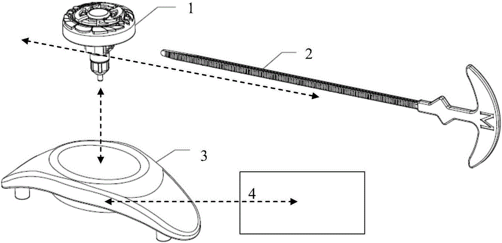
[0026] In the embodiment provided by the present invention, the rotating body is a spinning top for sports or toys, such as figure 1 As shown, a gyro rotation duration measurement system with spring contacts using RFID technology includes: gyro body 1; rack 2; competition area base 3; computer terminal and/or mobile smart device APP 4.
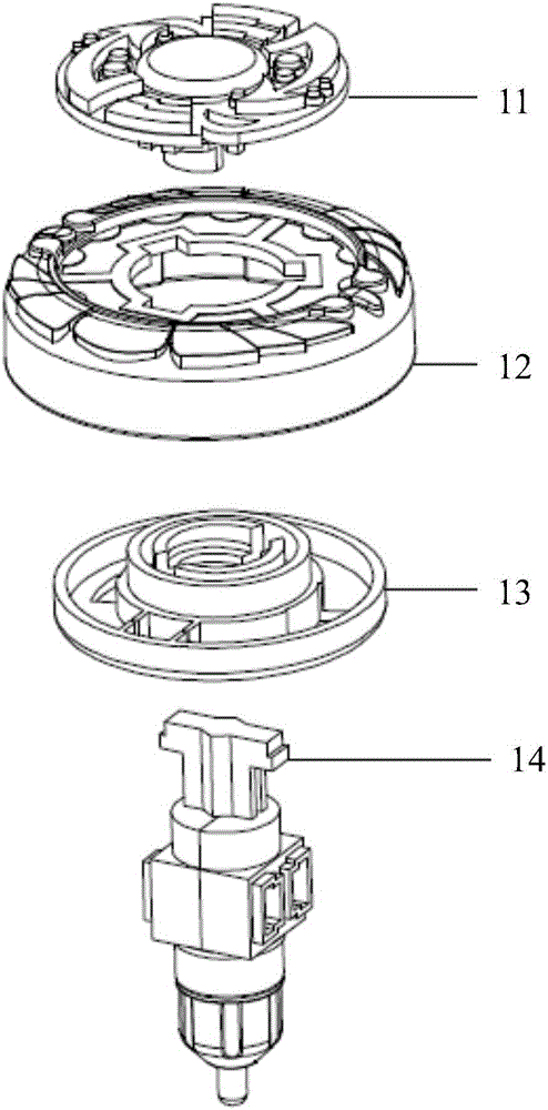
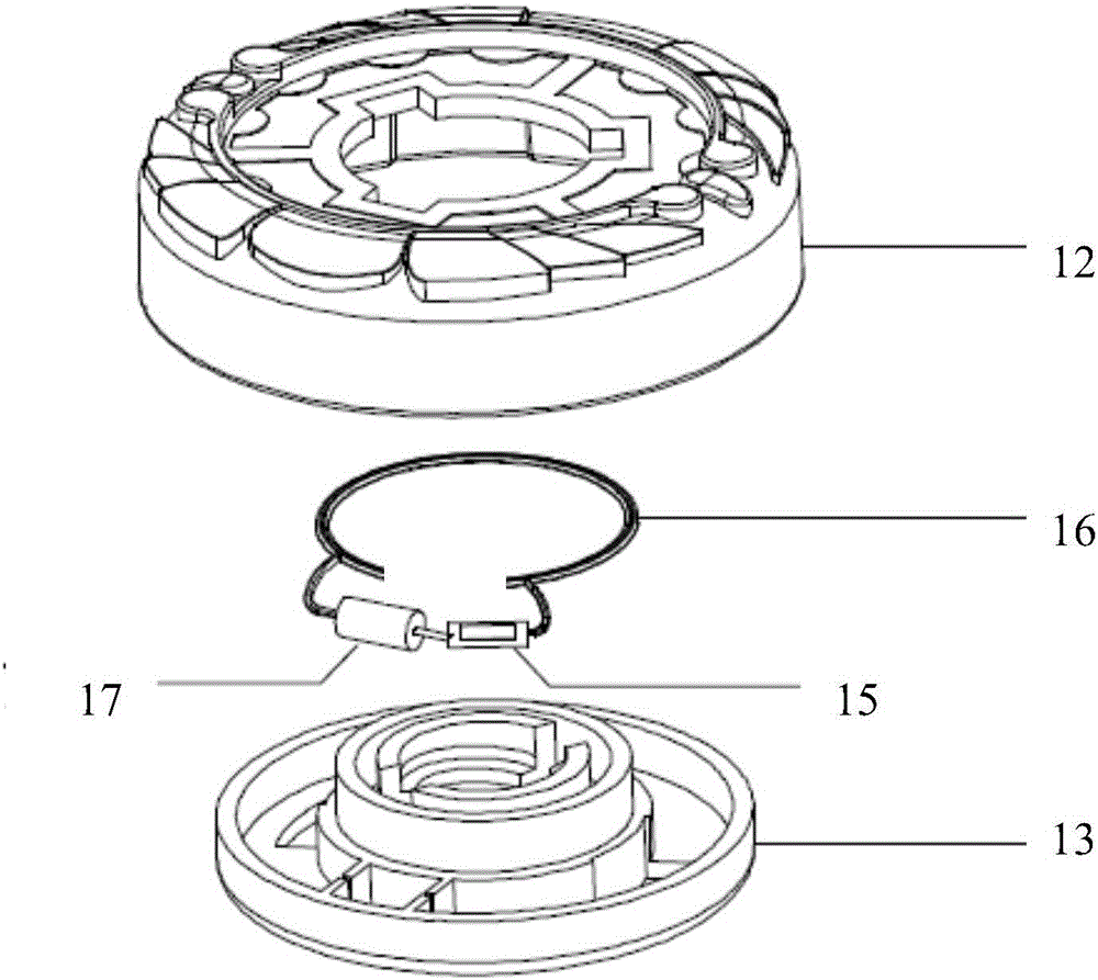
[0027] exist Figure 2-4 , the structure of the top body is further disclosed. The top body 1 is composed of a top cover 11, an attack ring 12, a fission ring 13 and a top tip 14. The top cover 11, attack ring 12, fission ring 13 and top tip 14 are arranged from top to bottom connected in turn, in image 3 Among them, the gyro body 1 is provided with an RFID tag and an IC chip 15, and the RFID tag and the IC chip 15 have a ring-shaped antenna 16, and the antenna 16 is stuck between the attack ring 12 and the fission ring 13, and one end of the ring antenna 16 Connect with RFID tag and IC chip 15, the other end is connected with vibration switch 17, the side of vibration switch 17 is provided with the China Unicom contact that matches with RFID tag and IC chip 15, in Figure 4 Among them, the spring mouth of the gyro tip 14 is formed by engaging two symmetrical left and right covers 141, the upper part of the shaft column 142 is fixedly connected with the positioning piece bayonet 143 through the shaft center piece 148, the lower part is covered with a gear 144, and the bottom of the shaft column 142 From top to bottom, a bare body rotating part 145, a fixing cap 146 and a bottom vertebral body tip 147 are fixed by the shaft core part 148.
[0028] Figure 5 It shows the structure of the rack 2, which is composed of a handle and a pull bar. The handle is set on the top of the side of the pull bar, so that the rack as a whole is in the shape of a "T". The inner wall features matching protrusions.
[0029] Image 6 The structure of the competitive area base 3 is shown, the support 31 of the competitive area base is a triangular support, the center of the support 31 is the RFID tag reading area, and the RFID tag reading area is respectively stuck on the top of the support 31 and the lower cover 33 by a transparent material. The bottom forms a hollow area, and the induction antenna 34, PCBA assembly printed circuit board 35, RFID tag reader 36 and battery 37 are installed from top to bottom in the area, and the induction antenna 34, PCBA assembly printed circuit board 35, RFID tag reading The device 36 and the battery 37 are connected in turn.
[0030] The basic working principle of the present invention is that when the gyro is stationary, the vibration switch is disconnected, and the RFID tag is not fully connected with the IC chip and the antenna. At this time, the RFID tag will not be recognized by the RFID reader; Under the action of centrifugal force, the vibration switch is short-circuited, so that the RFID tag is connected with the IC chip and the antenna, and is recognized by the RFID tag reader. The RFID tag reader calculates the gyroscope from static to rotating or vibrating by timing the recognition time. Duration and or period between rotation or vibration cessation. The specific implementation is described as follows:
[0031] when working, such as Figure 1-6 As shown, press and hold the top cover 11 or attack ring 12 of the top body 1, insert the rack 2 into the spring opening of the top body 1, pull out the rack 2 and loosen the top cover 11 or attack ring 12 of the top body 1 at the same time , so that the gyroscope body 1 rotates on the RFID tag reading area of ​​the competition area base 3; since the RFID tag reader 36 is housed, the RFID tag reading area can simultaneously identify multiple RFID tags and IC chips 15 above;
[0032]At this time, because the RFID tag and the IC chip 15 (tag) (passive or active tag) are housed in the gyroscope body 1, each tag has a globally unique ID (GUID), and the tag has a storage function, which can be passed through The radio frequency technology reads and writes the tag; the relevant information of the gyro body 1 is stored on the Tag; the RFID tag reader 36 can identify the gyro body 1 by reading the relevant information of the tag, and transmit it to the computer terminal and, Or display on the mobile smart device APP4;
[0033] Judgment of gyro rotation time:
[0034] like image 3 As shown, when the gyroscope body 1 starts to rotate, because of the centrifugal force, the contact of the vibration switch 17 will be in contact with the RFID tag and the IC chip 15, so that the tag antenna 16 is connected, so it can be read by the RFID tag reader 36 at the bottom. It is recognized that timing starts at this time, and the starting time is ts;
[0035] When the gyroscope body 1 starts to reduce the rotating speed due to external factors, when it is about to stop, due to the loss of the support of centrifugal force, the contact of the vibration switch 17 is disengaged, and the tag antenna 16 is disconnected. At this time, the RFID tag reader 36 at the bottom will If the tag cannot be recognized, the timing ends at this time, and the end time is te. Then the rotation time of the gyroscope Tx=te-ts;
[0036] Bluetooth, infrared, WIFI and other wireless transmission technologies are used to realize data connection, so that the results are displayed on the computer terminal and/or mobile smart device APP 4.

PUM

no PUM

Description & Claims & Application Information

We can also present the details of the Description, Claims and Application information to help users get a comprehensive understanding of the technical details of the patent, such as background art, summary of invention, brief description of drawings, description of embodiments, and other original content. On the other hand, users can also determine the specific scope of protection of the technology through the list of claims; as well as understand the changes in the life cycle of the technology with the presentation of the patent timeline. Login to view more.

Similar technology patents

Method for deodorizing garbage by utilizing composite microbial agent

Owner:GUANGXI HONGSHENGYUAN ENVIRONMENTAL PROTECTION CO LTD

Classification and recommendation of technical efficacy words

  • Novel idea
  • Ingenious structure

Method for preparing natural nontoxic adhesive for wood use

Owner:武汉正轩宇生物科技有限公司

Oil spilling alarm buoy device

Owner:北京奥佳科技发展有限公司

Light source capable of supplying polychromatic light and method thereof

ActiveCN101592308AEliminate spoke flareIngenious structureElectric lightingPicture reproducersSpokeLight beam
Owner:APPOTRONICS CORP LTD
Why Eureka
Try Eureka