3-phase separator with high thermal efficiency

A three-phase separator, high thermal efficiency technology, used in liquid separation, separation methods, dispersed particle separation, etc., can solve problems such as independent space, and achieve the effect of saving costs and improving thermal efficiency

Inactive Publication Date: 2016-10-26
TAEKYUNG
View PDF8 Cites 3 Cited by
  • Summary
  • Abstract
  • Description
  • Claims
  • Application Information

AI Technical Summary

Problems solved by technology

[0007] Therefore, it is necessary to manufacture an additional heat exchanger, and there are problems such as requiring a separate space

Method used


Image

  • 3-phase separator with high thermal efficiency
  • 3-phase separator with high thermal efficiency
  • 3-phase separator with high thermal efficiency

Examples


Embodiment Construction

[0040] For the advantages, features, and implementation methods of the present invention, please refer to the accompanying drawings and the embodiments described below. However, the present invention is not limited to those set forth herein, and the embodiments can be embodied in various forms, rather, these embodiments are fully enabled by the present invention, and the scope of the present invention will be fully provided to persons having ordinary knowledge in the technical field to which the invention pertains. For those who, the present invention is only the definition of the scope of the claims of the application. The same reference numerals below refer to the same names throughout the specification.

[0041] Therefore, with reference to the following drawings, technical embodiments of the present invention are described in detail based on a three-phase separator with high thermal efficiency. The description of the present invention is for reference only, and detailed d...


PUM


Abstract

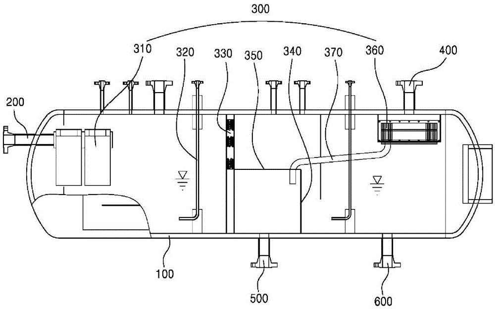
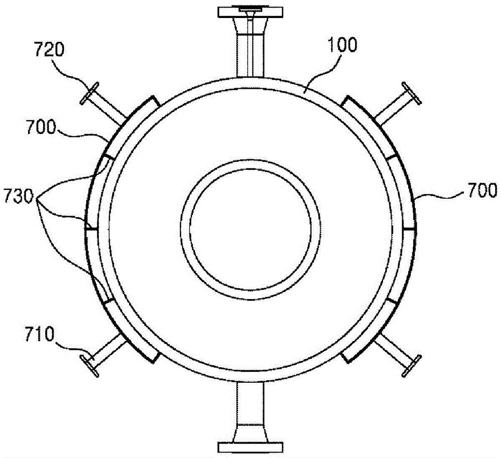
The present invention relates to a separator device, in particular, a 3-phase separator capable of efficiently separating three primary liquids mixed up by water, oil and gas, which accurately refers to a pressure vessel. The pressure vessel is provided with an injection port disposed on one side of the pressure vessel and used for injecting the three primary liquids mixed up by water, oil and gas into the pressure vessel; a separating device used for gradually separating the three primary liquids in the pressure vessel; a first flow outlet arranged on one side of the pressure vessel and used for discharging the separated gas; a second flow outlet connected with the bottom of the pressure vessel and used for discharging the separated water; and a third flow outlet arranged adjacent to the second flow outlet and used for discharging the separated oil. An inlet part and an outlet part are arranged to surround one part of the outer surface of the pressure vessel.

Description

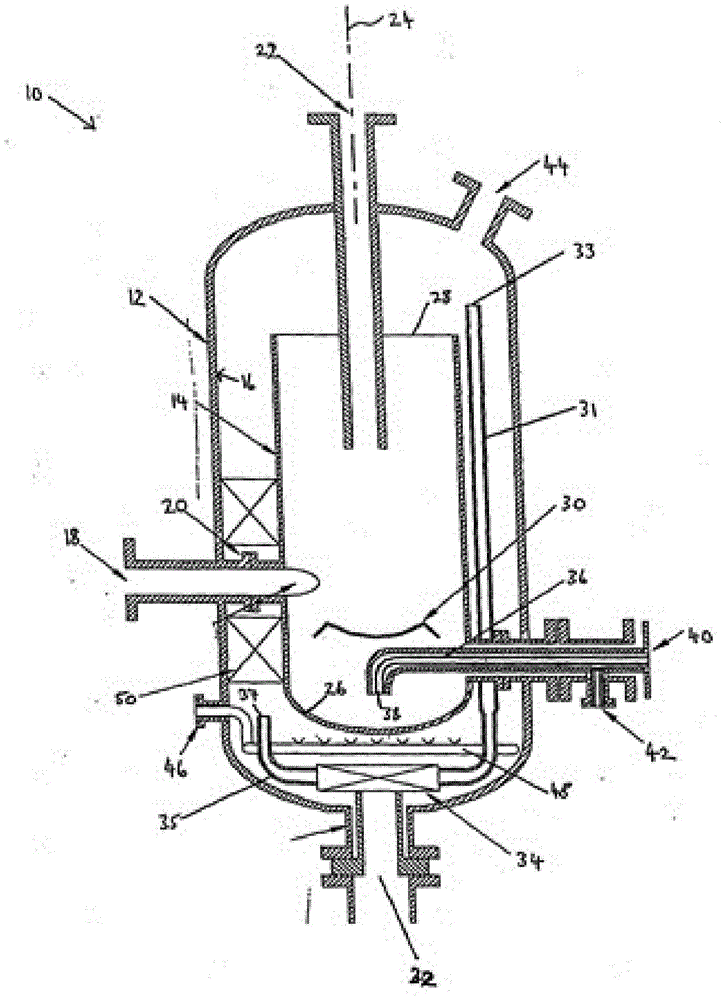
technical field [0001] The present invention relates to a separator device, and specifically refers to a three-phase separator device capable of efficiently separating three raw liquids mixed with water, oil and gas. Background technique [0002] Separators generally refer to the separation of two or more mixed substances into their respective components, and are suitable for various fields such as refining petroleum or sludge treatment. [0003] The function of the three-phase separator is to separate oil, water and gas, and the utility model patent No. 10-1287374 (registered on July 12, 2013) related to the present invention includes "for separating liquid / liquid / gas / Separator for mixtures such as solids". [0004] figure 1 It is a structural cross-sectional view of the separator, as shown in the figure, which separates the mixture of the first fluid, the second fluid with a higher density than the first fluid, and the solid into the first fluid, the second fluid, and t...

Claims


Application Information

Patent Timeline
Patent Type & Authority Applications(China)
IPC IPC(8): B01D45/16B01D45/08B01D17/028C02F1/40
Inventor 李洙泰郑载勳金叔姬吴聖龙崔与蔚朴成镐
Owner TAEKYUNG
Why Eureka
Try Eureka