Apparatus for measuring the flow rate of a fluid

a flow rate and apparatus technology, applied in the direction of volume/mass flow measurement, measurement devices, instruments, etc., can solve the problems of not having an energy-efficient means for measuring the flow rate, affecting the performance of elements, and affecting the accuracy and repeatability of positioning elements within the pipe bore, etc., to achieve efficient thermal interchange, facilitate mass production, and high surface area

Active Publication Date: 2014-02-18
SERVOMEX GRP LTD
View PDF13 Cites 9 Cited by
  • Summary
  • Abstract
  • Description
  • Claims
  • Application Information

AI Technical Summary

Benefits of technology

[0017]a heated reference element arranged in the measure cell so as to have reduced exposure to fluid flowing through the fluid flow path compared to the measure element, wherein the measure and reference elements are symmetrically or equivalently arranged within the measure cell such that they experience an equivalent heat transfer environment, other than the heat transfer effects due to fluid flowing through the fluid flow path;
[0020]In one embodiment, a symmetrical arrangement of the measure and reference elements involves equivalent geometry including equal distances from the sidewalls of the measure cell. In one embodiment, the measure and reference elements have equal dimensions, electrical conduction and thermal conduction. In one embodiment, a heat exchanger is arranged between the measure and reference elements to enable exchange of heat between the measure and reference elements. In one embodiment, the measure and reference elements have a planar geometry. This enables a compact design and a relatively large surface area for efficient thermal interchange between the measure and reference elements.
[0022]In one embodiment, the measure and reference elements are essentially identical with matching thermal characteristics, so that the shape, size, thermal and electrical conduction, radiation emissive characteristics and thermal mass of the elements are indistinguishable. The measure and reference elements are planar and may be of thick film, thin film, resistor wire or similar construction. The use of planar measure and reference elements enables compact design and high surface area for efficient thermal interchange between measure and reference elements and also between the measure element and the incoming fluid and facilitates mass production in a repeatable way. Thermal exchange between the reference and measure elements is used to optimise noise rejection due to common mode background thermal effects. The cell design, materials and dimensions as well as the flow inlet and outlet means may be optimised for the required application (such as for particular gas compositions) to give the required sensitivity and flow range.
[0027]a cooled reference element arranged in the measure cell so as to have reduced exposure to fluid flowing through the fluid flow path compared to the measure element, wherein the measure and reference elements are symmetrically or equivalently arranged within the measure cell such that they experience an equivalent heat transfer environment, other than the effects due to fluid flowing through the fluid flow path;

Problems solved by technology

However, as for the previously described method, it is not an energy efficient means for measuring the flow rate and is mainly used for gases at low flow rates, often in a bypass arrangement.
An alternative mechanical arrangement of this design with higher sensitivity is to mount the heating and sensing elements in the sample stream within the pipe, however, it is much more difficult to accurately and repeatably position the elements within the pipe bore and the elements' performance may be significantly affected by high sample stream velocity, particulates or entrained fluids condensing out.
Thin filament wires or thin film devices will give fast time responses and large signals when compared to thicker wires, but they are fragile and will be subject to error if there are particulates or entrained fluids within a gaseous mixture which could deposit on the wire.
They also have limited flow ranges unless used in bypass mode.

Method used


Image

  • Apparatus for measuring the flow rate of a fluid
  • Apparatus for measuring the flow rate of a fluid
  • Apparatus for measuring the flow rate of a fluid

Examples


Embodiment Construction

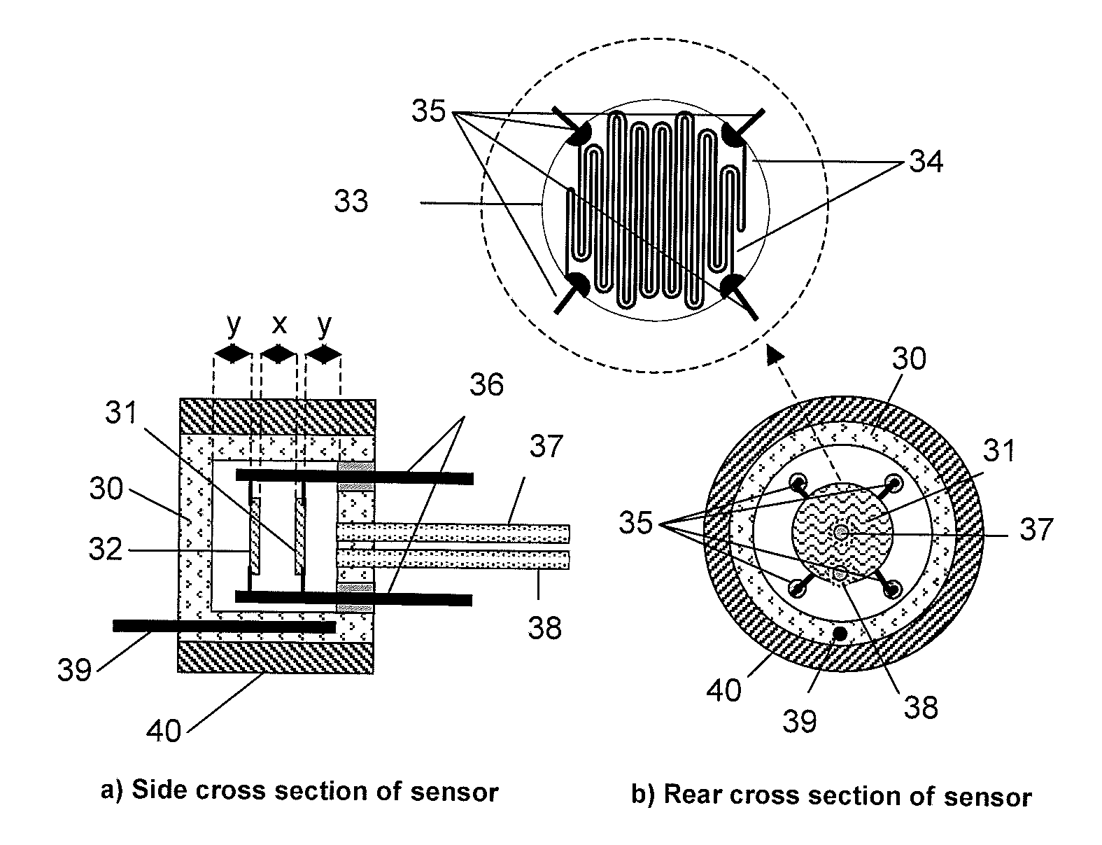
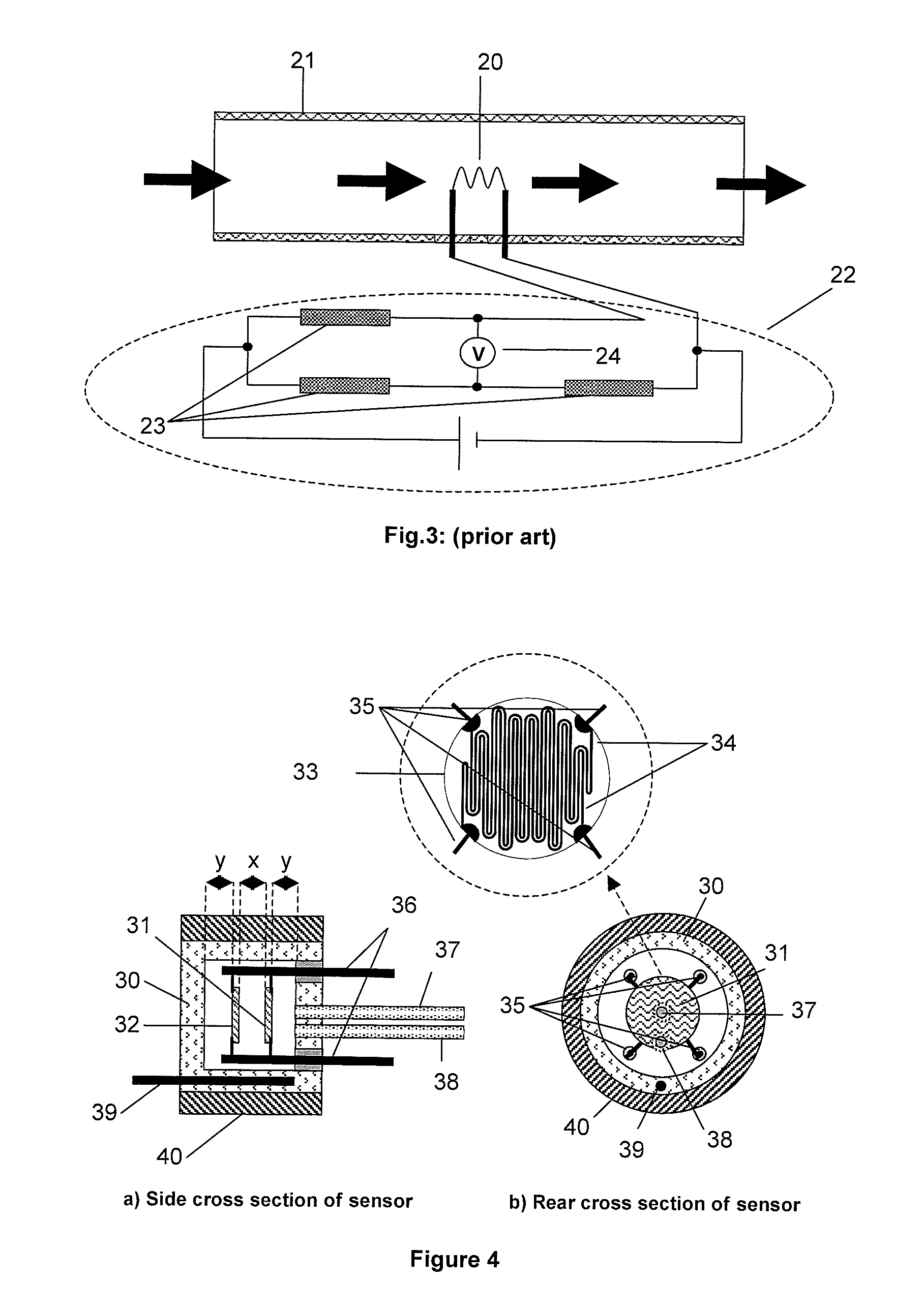
[0044]An illustration of a first embodiment is shown in FIGS. 4a and 4b, although alternative designs containing the same essential features could be constructed. A measurement cell (30) contains a measure element (31) and reference element (32), both of which are thick film printed resistors on ceramic discs. The measure and reference elements have at least one resistor printed on the substrate. The item in FIG. 4 that is expanded in a separate ‘balloon’ shows a ceramic disc (33), on which two platinum resistor tracks are printed (34). Thin platinum or platinum / iridium wires (35) are used to connect these resistors to the electrodes (36) via welding. Precise positioning of the elements is important to this embodiment and this is achieved by using precision mounting apparatus or other suitable means. In some embodiments, the elements have a protective glaze layer. The measure and reference discs are aligned with the resistor tracks perpendicular to each other, so that the measure an...


PUM


Abstract

Provided is a compact apparatus for measuring the flow rate of a fluid. The apparatus includes a heated measure element and a heated reference element which are in substantially the same thermal environment within a measure cell, except that the measure element is situated in the path of the cooling fluid flow and the reference element is sheltered from this direct fluid flow. These elements are arranged as parallel and concentric planar elements that are essentially identical to each other with matching thermal characteristics. The elements are electrically connected in a Wheatstone bridge arrangement. Thermal exchange between the reference and measure elements is used to optimise noise rejection due to common mode background thermal effects. Measured parameters from the bridge can be used to derive the fluid flow rate.

Description

CROSS REFERENCE TO RELATED APPLICATIONS[0001]This application claims priority under 35 U.S.C. §119 to Great Britain patent application No. GB1009444.9 filed on Jun. 4 2010, which is incorporated herein by reference.FIELD OF INVENTION[0002]The present invention provides apparatus for measuring the flow rate of a fluid, by measuring differential effects of a fluid flow on a measure element and a reference element.BACKGROUND OF THE INVENTION[0003]Steady state thermal fluid flow meters are primarily mass flow based devices, where the rate of heat transfer (dQ / dt) being measured will depend upon the rate of mass flow of the fluid with time (dM / dt) as well as the specific heat capacity at constant pressure (Cp), so that:[0004]ⅆQⅆt∝Cp⁢ⅆMⅆt.[0005]The volume flow rate (dV / dt) and mass flow rate of the fluid can be related via the density (ρ) such that:[0006]ⅆVⅆt=1ρ⁢ⅆMⅆt.[0007]Many thermal mass flow meters are based on the heat tracer principle. An illustration of a simple version is shown in...

Claims


Application Information

Patent Timeline
Patent Type & Authority Patents(United States)
IPC IPC(8): G01F1/68
CPCG01F1/6842G01F1/698G01F1/69G01F1/684
Inventor LOPEZ, MARTINHOBBY, JAMESAYLWARD, GARY ROBERTALIZADEH, BAHRAM
Owner SERVOMEX GRP LTD
Why Eureka
Try Eureka