Robot deburring system and method through visual inspection

A robotic system and visual inspection technology, applied in the field of deburring systems, can solve the problems of human harm, low efficiency and poor accuracy.

A robotic system and visual inspection technology, applied in the field of deburring systems, can solve the problems of human harm, low efficiency and poor accuracy.

CN106041948AActive Publication Date: 2016-10-26黑龙江哈工华粹智能装备有限公司

Image

  • Robot deburring system and method through visual inspection
  • Robot deburring system and method through visual inspection
  • Robot deburring system and method through visual inspection

Examples


Embodiment Construction

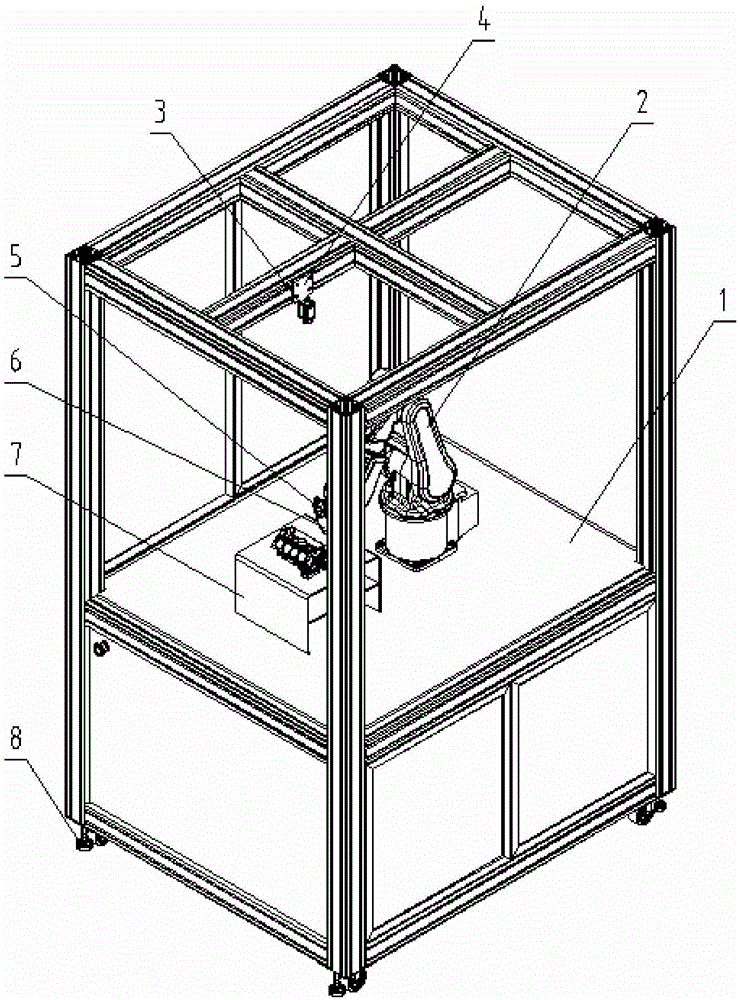
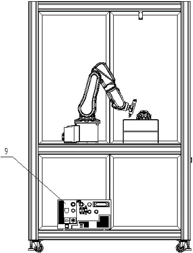
[0022] Such as Figure 1-2 As shown, the robot deburring system using visual inspection according to the present invention includes a robot installation frame 1, a robot system, a high-speed electric spindle system, a visual camera system, a PLC control module, and a workpiece placement platform 7 .

[0023] Further, the robot installation frame 1 is used as an installation platform for the installation and positioning of the robot 2 and the robot control box and other components, and plays a role in protecting the robot 2 and other components. The bottom of the installation frame 1 is equipped with four sets of composite casters 8, including adjustable feet and pulleys, so that the equipment can be moved freely, and the height of the installation frame 1 can be slightly adjusted.

[0024] The robot system is composed of a robot 2, a robot control box, and a teaching pendant. The robot 2 completes corresponding processing actions according to a pre-programmed program.

[0025...


PUM


Abstract

The invention provides a robot deburring system through visual inspection. The robot deburring system comprises a robot installation rack, a robot system, a high-speed electric spindle system, a visual camera system, a PLC control module and a workpiece placing platform. At the same time, the invention further provides a robot deburring method through visual inspection, and the robot deburring system through visual inspection is applied. According to the robot deburring system through visual inspection, the advantages that the working efficiency is high, the precision is high, deburring is thorough, and a worker can be prevented from being hurt by removed burrs are achieved; and meanwhile, the visual camera system is adopted by the system, and when a to-be-machined component is replaced, a coordinate system of the workpiece does not need to be revised by the worker, so that robot machining becomes easy, and the requirements for high efficiency and high quality of machining at present are met.

Description

technical field [0001] The invention relates to a deburring system for industrial parts, in particular to a robot deburring system using visual inspection. The invention also relates to a deburring method using the system, especially based on a visual camera using visual detection, through cooperation with a robot, the process of part identification and deburring can be automatically completed. Background technique [0002] At present, metal parts will produce burrs during the machining process. The existence of these burrs not only affects the appearance of the parts, but also affects the subsequent use, assembly, performance and service life. Therefore, the deburring of parts is very important; the existing deburring The method of deburring is mainly through manual and mechanical processing. However, these traditional deburring methods have many disadvantages, such as low efficiency, poor accuracy, unclean deburring, and a large amount of flying debris that is harmful to ...

Claims


Application Information

Patent Timeline
26 Oct 2016
Publication
CN106041948A
IPC
B25J11/00; B25J19/04; B24B9/00; B24B49/12
CPC
B24B9/00; B24B49/12; B25J11/006; B25J19/04
Inventors
李增强; 白相林