Restaurant robot
A robot and restaurant technology, applied in the field of robots, can solve the problems of high cost of service robots, inconvenient maintenance and repair of service robots, etc., and achieve the effect of flexible movement, simple structure and stable performance
- Summary
- Abstract
- Description
- Claims
- Application Information
AI Technical Summary
Problems solved by technology
Method used
Image

Examples
specific Embodiment approach 1
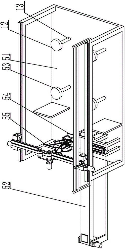
[0011] Specific implementation mode one: combine Figure 1 to Figure 5 Illustrate, a kind of restaurant robot described in this embodiment, it comprises base 51, dish transmission mechanism 52, dish storage table 53, dish grasping mechanism 54, lateral movement mechanism 55 and longitudinal movement mechanism 56, and longitudinal movement mechanism 56 is installed on On the base 51, the transverse movement mechanism 55 is arranged on the longitudinal movement mechanism 56, the dish grabbing mechanism 54 is installed on the bottom end of the transverse movement mechanism 55, and the end of the dish transmission mechanism 52 near the base 51 is arranged on the base 51, The dish storage table 53 is arranged on the base 51 .
specific Embodiment approach 2
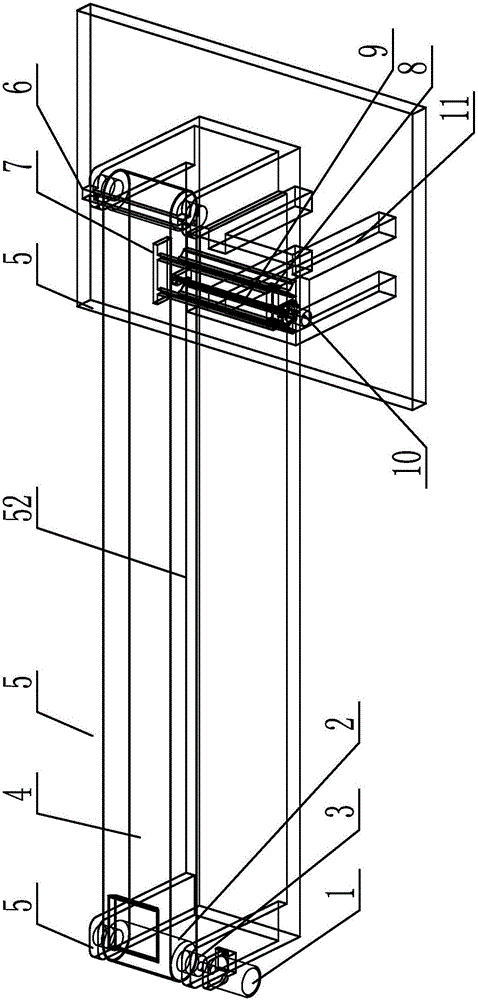
[0012] Specific implementation mode two: combination figure 1 with figure 2 Illustrate, the restaurant robot described in this embodiment, the dish transmission mechanism 52 includes the first transmission motor 1, the transmission belt 4, the first transmission mechanism support frame 5, the positioning block 6, the push plate 7, the two-way transmission mechanism screw 9, the first transmission mechanism Two transmission motors 10, the second transmission mechanism support frame 11, two transmission pulleys 2, two transmission pulley shafts 3 and two guide rail blocks 8, each transmission pulley shaft 3 is fixedly fitted with a transmission pulley 2, two transmission pulley shafts 3 They are respectively arranged on the support frame 5 of the first transmission mechanism, and each conveyor pulley shaft 3 is rotatably connected with the support frame 5 of the first transmission mechanism. The two conveyor pulleys 2 are sleeved with a conveyor belt 4, and one end of one of th...
specific Embodiment approach 3
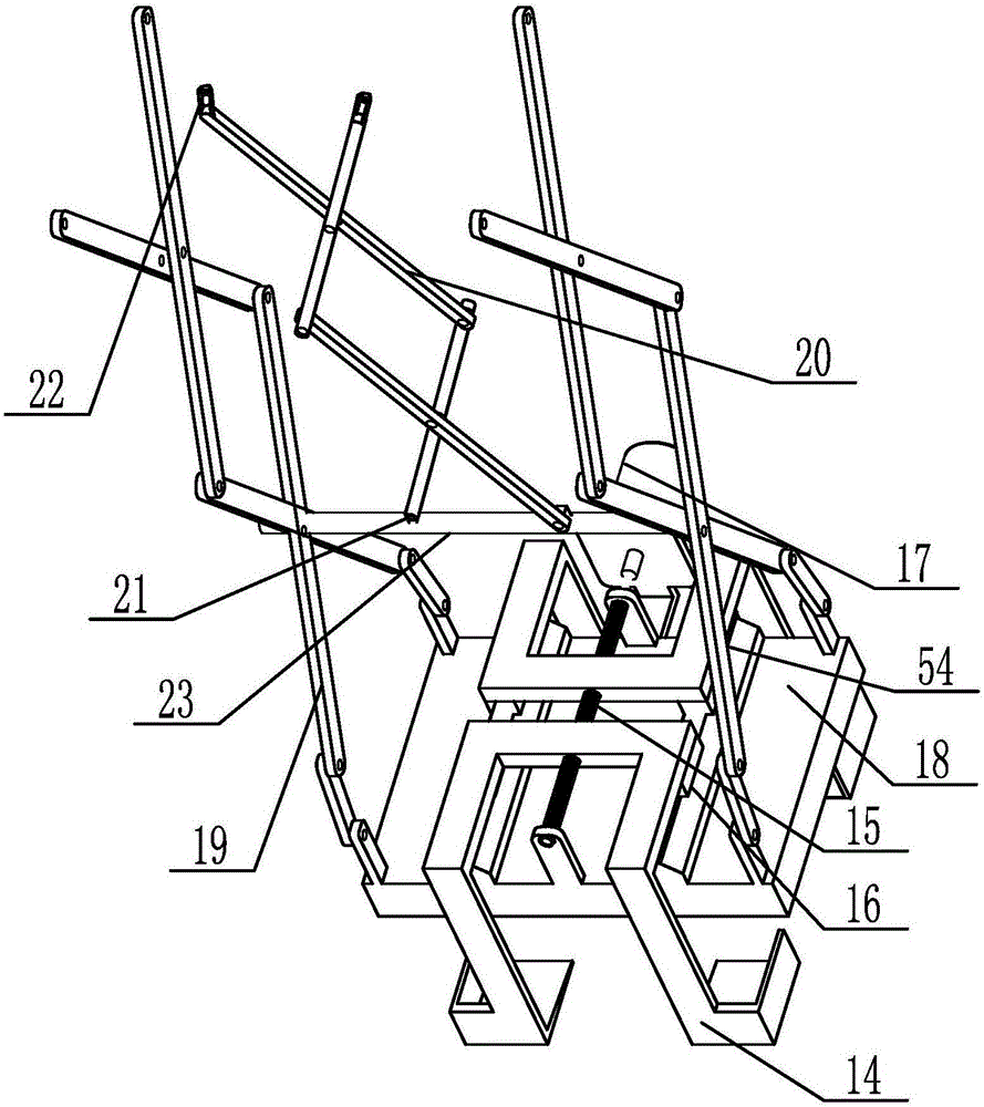
[0013] Specific implementation mode three: combination figure 1 with Figure 5 Illustrate, the restaurant robot described in this embodiment, the longitudinal movement mechanism 56 includes two longitudinal guide rail frames 32, two longitudinal scroll wheel shafts 34, two longitudinal movement frames 33, two longitudinal mechanism drive motors 35 and two longitudinal mechanism Roller 36, two longitudinal rail frames 32 are relatively fixedly installed on the base 51, a longitudinal rolling wheel shaft 34 is installed on each longitudinal moving frame 33, and the longitudinal moving frame 33 is rotationally connected with the longitudinal rolling wheel shaft 34, each longitudinal rolling A longitudinal mechanism roller 36 is fixedly sleeved on the axle 34, and the output end of each longitudinal mechanism driving motor 35 is fixedly connected with an end of a longitudinal rolling wheel axle 34 respectively, and the motor seat of each longitudinal mechanism driving motor 35 is ...
PUM
 Abstract
Description
Claims
Application Information
 - R&D
- Intellectual Property
- Life Sciences
- Materials
- Tech Scout
- Unparalleled Data Quality
- Higher Quality Content
- 60% Fewer Hallucinations
Browse by: Latest US Patents, China's latest patents, Technical Efficacy Thesaurus, Application Domain, Technology Topic, Popular Technical Reports.
© 2025 PatSnap. All rights reserved.Legal|Privacy policy|Modern Slavery Act Transparency Statement|Sitemap|About US| Contact US: help@patsnap.com