Brake pump and its application on loader

A brake pump and brake caliper technology, applied in the arrangement of pumps/compressors, mechanical equipment, vehicle parts, etc., can solve the problems of short moving distance of the brake pedal, inconvenient use, inconvenient maintenance and disassembly, etc., to save driving intensity, improve The effect of driving safety and convenient maintenance and disassembly

Active Publication Date: 2018-03-20
莱州虎威机械科技有限公司
View PDF7 Cites 0 Cited by
  • Summary
  • Abstract
  • Description
  • Claims
  • Application Information

AI Technical Summary

Problems solved by technology

In order to reduce the cost, one brake chamber of the improved brake pump is equipped with two sets of pistons in series, and one brake chamber forms two liquid outlet channels, and each liquid outlet channel controls two brake calipers. Although the brake pump has a compact structure, However, once the brake cavity shell is damaged, the brakes of the whole vehicle will fail.
Therefore, the applicant improved again by using one air chamber to simultaneously control two sets of pistons in two brake chambers connected in parallel. Inconsistencies in the hydraulic pressure lead to uneven stress on the rubber cup in the air chamber, frequent failures, and poor reliability
[0004] In addition, the above two improved brake pumps have a one-way valve between the liquid storage tank and the brake chamber, and the brake fluid can only flow from the liquid storage tank to the brake chamber. There is more and more brake fluid in the brake chamber, and the moving distance of the brake pedal is getting shorter and shorter. If necessary, it is necessary to manually adjust the brake fluid in the brake chamber, which brings inconvenience to the use
At the same time, the liquid storage tank and the brake chamber are fixedly connected, which brings inconvenience to maintenance and disassembly

Method used


Image

  • Brake pump and its application on loader
  • Brake pump and its application on loader
  • Brake pump and its application on loader

Examples


Embodiment Construction

[0052] The following will be described in detail in conjunction with the accompanying drawings and embodiments.

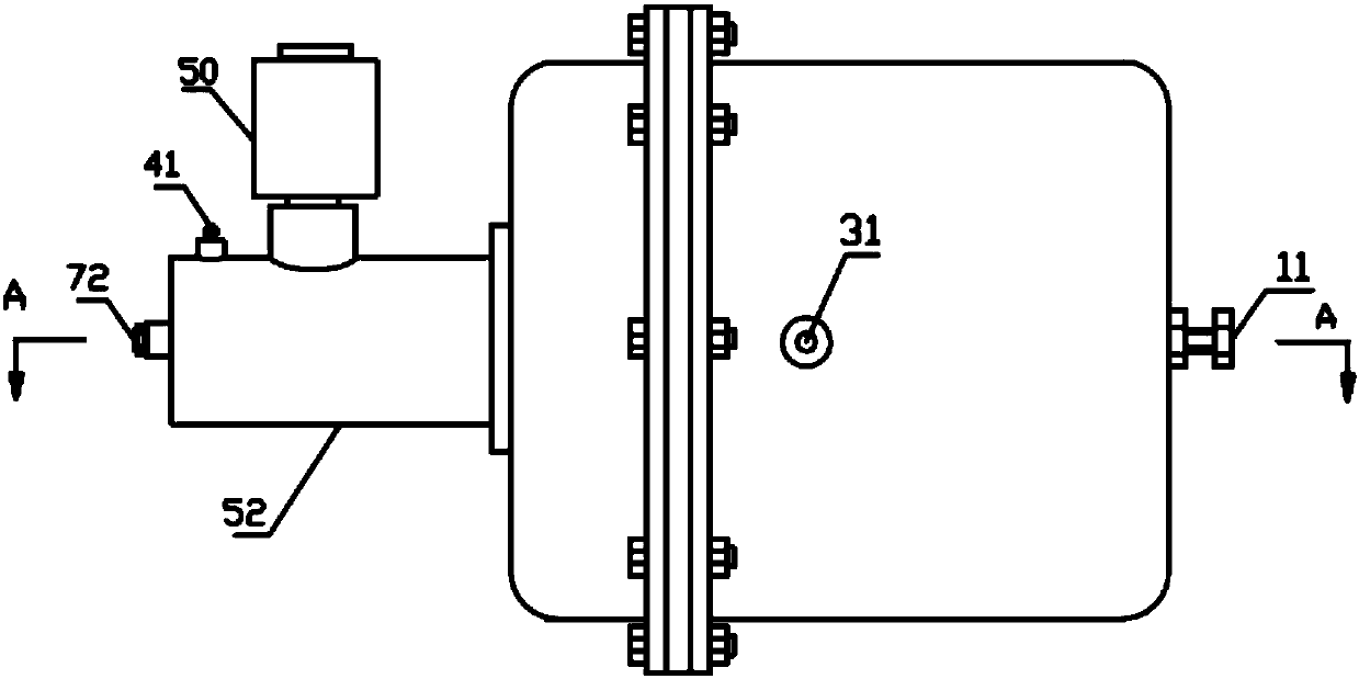
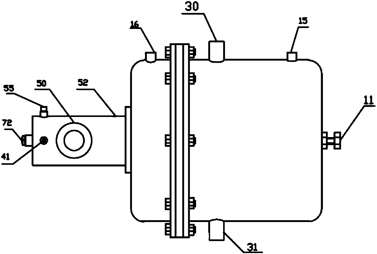
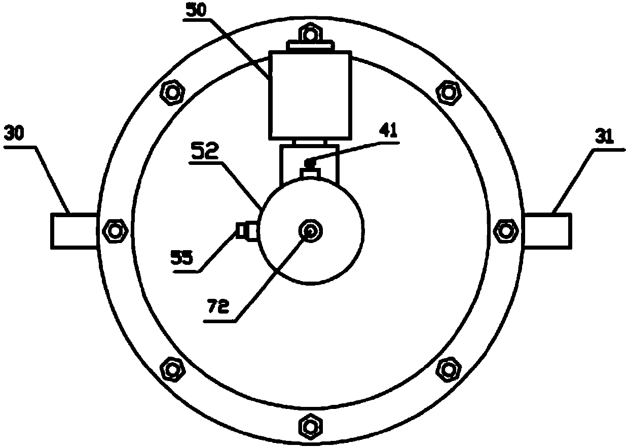
[0053] Such as Figure 1 to Figure 7 As shown, the brake pump of the present invention includes a brake pump housing, and a brake chamber, a service brake chamber and a parking brake chamber are arranged in the brake pump housing. In this embodiment, the brake chamber housing 52 is provided with a brake moving cavity. The service brake chamber is located on the left side of the parking brake chamber, and the brake chamber is located on the left side of the service brake chamber; the service brake chamber is provided with a first rubber cup 5, and the first rubber cup 5 applies the service brake The cavity is divided into a service brake left chamber 33 and a service brake air storage chamber 2, the service brake air storage chamber 2 is located on the right side of the service brake left chamber 33, and the service brake air storage chamber 2 is provided with a se...


PUM


Abstract

The invention discloses a breaker pump and applications thereof on loaders. The breaker pump comprises a brake chamber, a driving vehicle brake chamber and a stopped vehicle brake chamber; the driving vehicle brake chamber is provided with a first rubber skin cup; the driving vehicle brake chamber is divided into a driving vehicle brake left chamber and a driving vehicle brake chamber air receiver by the first rubber skin cup; the stopped vehicle brake chamber is provided with a first piston; the stopped vehicle brake chamber is divided into a stopped vehicle brake air receiver and a stopped vehicle brake right chamber by the first piston; a first push rod is installed at the left side of the first piston; a main spring is installed at the right side of the first piston; the brake chamber is provided with a liquid outlet channel; the brake chamber is provided with a second piston; a first reset spring is installed at the left side of the second piston; a second push rod is installed at the left side of the first rubber skin cup; the second push rod is sleeved by an auxiliary spring; the brake chamber is provided with a liquid outlet chamber; the liquid outlet chamber is communicated with the brake chamber; a liquid storage tank is installed above the liquid outlet chamber; the liquid outlet chamber is provided with a first control valve; the connection or disconnection of the inner chamber and the liquid outlet chamber of the liquid storage tank are controlled by the first control valve. The breaker pump has the advantages of good braking effect, safe use and high reliability.

Description

technical field [0001] The invention relates to a brake pump and its application on a loader, belonging to the technical field of the loader brake pump. Background technique [0002] The parking brake of the existing loader adopts the central disc brake. The brake disc is fixed on the transmission shaft and operated mechanically. The brake device can only be used after the loader has stopped. It is easy to cause damage to the drive shaft and axle; if the loader is too heavy or parked on a slope, it is easy to cause parking failure and accidents. In addition, once the handbrake mechanism or transmission shaft fails, the brakes will fail; when driving, if any components such as air pumps, pipelines, air storage tanks, brake valves, etc. fail, the brakes will fail, which is very prone to accidents. [0003] In view of the above defects, the applicant has improved the air chamber and brake chamber of the brake pump. In order to reduce the cost, one brake chamber of the improve...

Claims


Application Information

Patent Timeline
Patent Type & Authority Patents(China)
IPC IPC(8): B60T13/14B60T17/02F16D65/22F16D121/10F16D121/06
CPCB60T13/14B60T17/02F16D65/22F16D2121/06F16D2121/10
Inventor 聂瑞波
Owner 莱州虎威机械科技有限公司
Why Eureka
Try Eureka