
A small trolley for collecting chips and its use method

A small trolley and row collection technology, which is applied in the direction of trolleys, trolley accessories, multi-axis trolleys, etc., can solve the problems of complex structure and inconvenient use, and achieve the effects of improving spring pressing effect, easy turning, and low production cost

Active Publication Date: 2018-11-06
MAANSHAN CHENGHONG MACHINERY MFG
View PDF1 Cites 0 Cited by
  • Summary
  • Abstract
  • Description
  • Claims
  • Application Information

AI Technical Summary

Problems solved by technology

[0006] Aiming at the problem of complex structure and inconvenient use of the dump truck dump lock existing in the prior art, the present invention provides a trolley for collecting and removing chips and its use method

Method used


Image

  • A small trolley for collecting chips and its use method
  • A small trolley for collecting chips and its use method
  • A small trolley for collecting chips and its use method

Examples


Embodiment 1

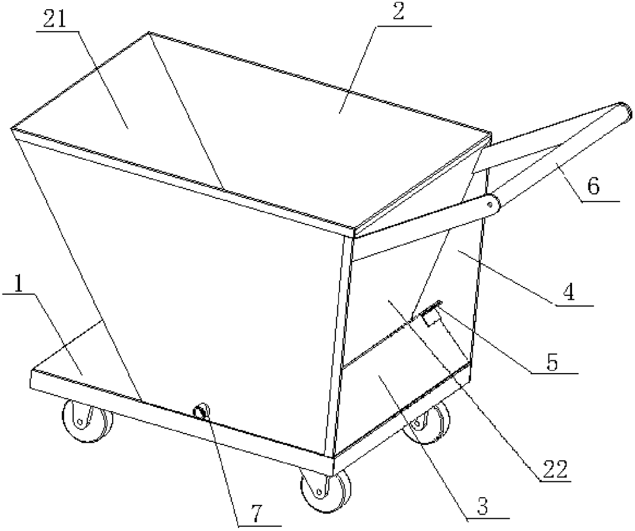
[0044] Such as figure 1As shown, a kind of chip-collecting trolley of this embodiment includes a flatbed vehicle surface 1 and a hopper 2, and also includes an elastic pressing plate 3 and a wing plate 4; the hopper 2 is a trapezoidal body with a large opening and a small bottom surface, including 1. The front plate 21 and the rear plate 22 which are inclined inwardly and gradually closed, and two side plates 23 perpendicular to the flatbed vehicle surface 1, wherein: the front plate 21 is connected with the flatbed vehicle surface 1 in an overturned manner; the bottom end of the elastic pressure plate 3 is connected to the flatbed vehicle The tail end of the surface 1 is connected by elastic pressure reset; there are two wing plates 4, which are the backward extending plates of the two side plates 23, protruding from the slope formed by the rear plate 22, and the inner sides of the two wing plates 4 are relatively symmetrically arranged. The positioning block 5 and the elasti...

Embodiment 2

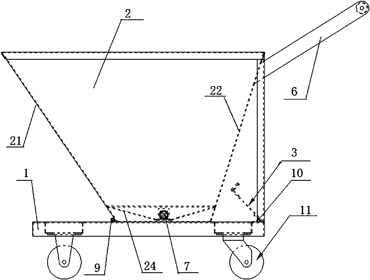
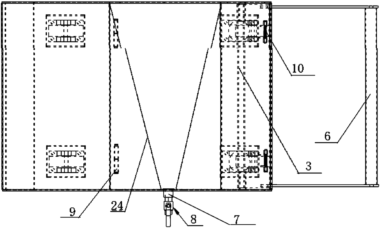
[0047] The basic structure of the chip-collecting trolley of this embodiment is the same as that of Embodiment 1, and the improvements are as follows: figure 2 with 3 As shown, the front panel 21 is connected to the flatbed vehicle surface 1 through a hinge hinge 9; Such as Figure 5 As shown, the spring 10 is a torsion spring, and the elastic pressing rods at both ends extend obliquely at an acute angle. The upper elastic pressing rod 101 is fixedly connected to the elastic pressing plate 3; the lower elastic pressing rod 102 is fixedly connected to the flatbed vehicle surface 1; Face 1 upper surface.

[0048] A method of using a chip collection trolley in this embodiment, the steps are:

[0049] A. Chip collection: push the trolley to the bottom of the discharge port of the chip conveyor to collect the chips of the machine tool;

[0050] B. Chip transportation: after the collection is full, replace another small trolley to pick up the material, pull the small trolley fu...

Embodiment 3

[0056] The basic structure of this embodiment is the same as that of embodiment 2, except that it also includes a frame-shaped push-pull rod 6, the fixed end of which is fixed on the upper part of the rear plate 22. The upper elastic pressing bar 101 and the lower elastic pressing bar 102 are all inwardly folded at a right angle to form a folding bar; the wing plate 4 is a right-angled triangular plate; The angle formed by the front plate 21 and the flat vehicle surface 1 is 30 degrees, and the angle formed by the rear plate 22 and the flat vehicle surface 1 is 80 degrees.

[0057] The chip collection and removal trolley of this embodiment is suitable for chips with a density of 5.0 to 5.5 after calculation. The steps for use are as follows:

[0058] A. Chip collection: push the trolley to the bottom of the discharge port of the chip conveyor to collect the chips of the machine tool;

[0059] B. Chip transportation: after the collection is full, replace another small trolley ...


PUM


Abstract

The invention discloses a chip collection and removal trolley and a use method thereof, and belongs to the technical field of machine tool chip removal. The chip collection and removal trolley comprises a platform trolley surface, a hopper, a spring pressing plate and wing plates. The hopper is in the shape of a trapezoid body with a big opening and a small bottom surface, and comprises a front plate and a rear plate which is inclined towards the interior of the platform trolley surface and narrowed gradually, and two side plates perpendicular to the platform trolley surface, wherein the front plate is connected with the platform trolley surface in an turning-over manner, and the bottom end of the spring pressing plate is connected with the tail end of the platform trolley surface in a spring-pressing reset manner; the two wing plates are inclined faces formed in a way of backward extending plates of the two side plates protruding out of the rear plate, locating pieces are arranged on the inner sides of the two wing plates oppositely symmetrically, and the spring pressing plate is located in a gap formed by the locating pieces and the rear plate after being reset. According to the trolley provided by the invention, the hopper is turned over or not through spring pressing and resetting of the spring pressing plate, the spring pressing plate has the function of locking the hopper before the hopper is turned over, the hand lifts the hopper and the foot stamps on the spring pressing plate to turn over the hopper, the hand and the foot are used cooperatively, and the operation is convenient.

Description

technical field [0001] The invention relates to the technical field of machine tool chip removal, in particular to a chip collection and removal trolley and a use method thereof. Background technique [0002] In the process of machine tool processing, semi-finished products will be processed, such as turning, milling, grinding, boring and other processes. During this process, iron chips will be generated, and metal chips and cutting fluid will be output from the machine tool outlet to chip removal. Machine (such as scraper chip removal machine), through the chip removal machine, metal chips will be generated during the working process of the metal machine tool, and the chips will be separated from the cutting fluid. [0003] After the swarf is separated, it is generally transferred away with a trolley or a filter assembly line. The cost of the filter assembly line is high and is suitable for large factories; small machine tool factories generally use a trolley for transfer. ...

Claims


Application Information

Patent Timeline
Patent Type & Authority Patents(China)
IPC IPC(8): B62B3/08B62B5/00
CPCB62B3/08B62B5/00
Inventor 汪宏杰
Owner MAANSHAN CHENGHONG MACHINERY MFG
Learn More