
Torsional Vibration Control System for Unloaded Body

A non-load-bearing body, torsional vibration technology, applied in the connection between the body and the frame, vehicle components, transportation and packaging, etc., can solve the problems of reducing the ride quality and comfort of the vehicle, and large torsional vibration.

Active Publication Date: 2019-07-30
CHINA AUTOMOTIVE ENG RES INST
View PDF7 Cites 0 Cited by
  • Summary
  • Abstract
  • Description
  • Claims
  • Application Information

AI Technical Summary

Problems solved by technology

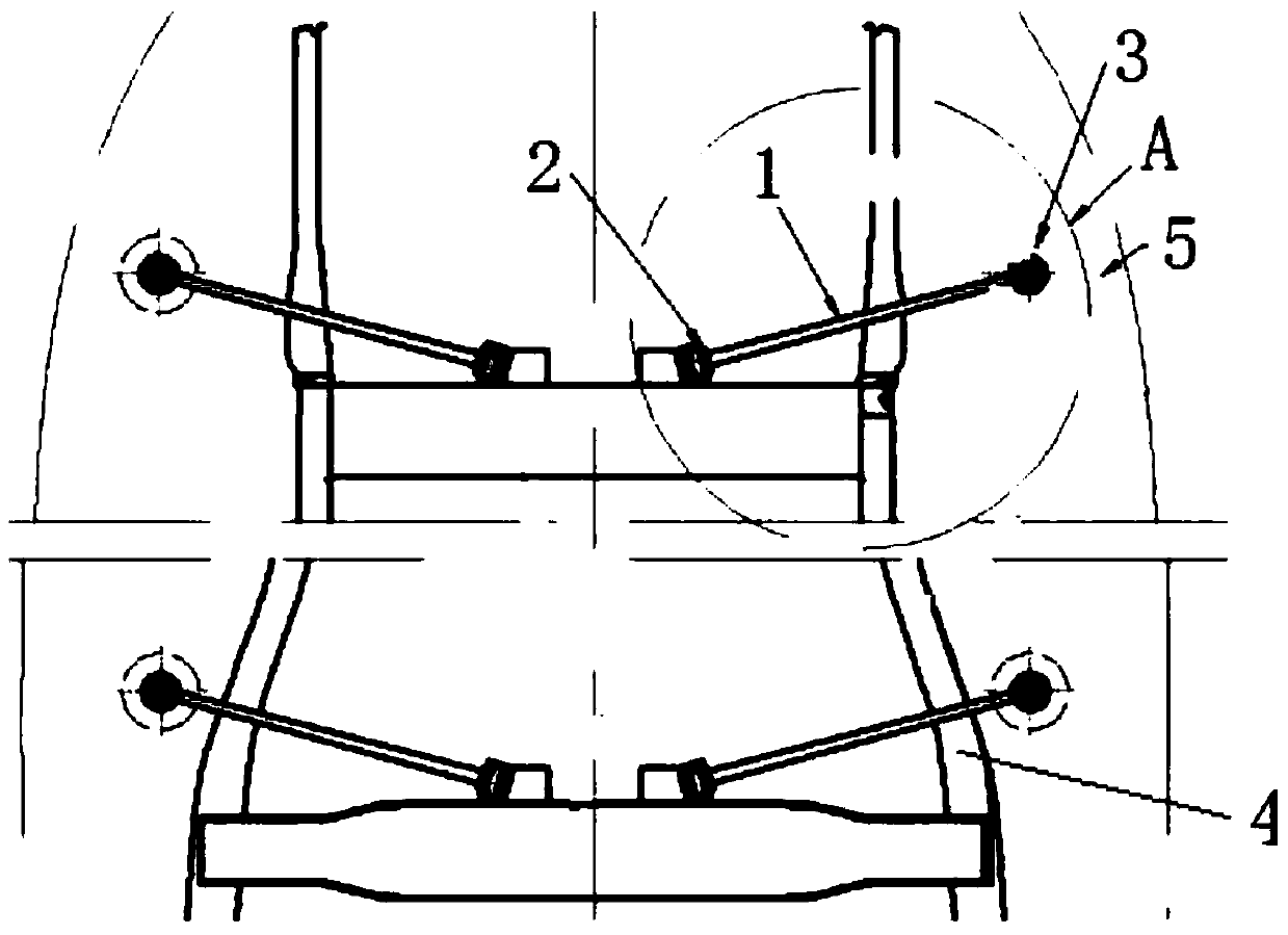
The body powertrain mount and the body mount constitute a complex multi-degree-of-freedom coupling vibration system. When driving on a normal road, the body shakes up and down (ie in the Z direction), but when the vehicle turns, brakes suddenly, ignites, stalls, and bumps Under working conditions such as the road surface, due to the instantaneous excitation of the road surface and the engine, the powertrain mount and the vehicle body mount generate coupled vibrations, causing the body to shake from side to side (ie, Y direction) or front and rear (ie, X direction), which greatly reduces the vehicle ride. quality and comfort
[0003] However, diesel engines are favored by automobile manufacturers and users due to their long life, economy and durability, high torque at low speed, high safety, and more environmental protection. Statistics show that the production of diesel vehicles is gradually increasing, and users have higher expectations for the NVH performance of diesel vehicles. There are many requirements, so it is urgent to solve the problem of large torsional vibration of the non-load-bearing body under special working conditions such as vehicle turning, sudden braking, ignition, flameout, and bumpy roads

Method used


Image

  • Torsional Vibration Control System for Unloaded Body
  • Torsional Vibration Control System for Unloaded Body

Examples


Embodiment Construction

[0012] Below by embodiment and in conjunction with accompanying drawing, the present invention will be further described:

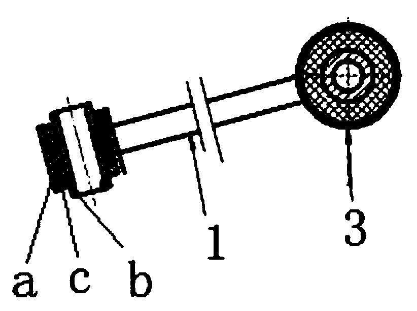
[0013] combine figure 1 , figure 2 As shown, a torsional vibration control system suitable for a non-load-bearing body, the non-load-bearing body includes a frame 4 and a body 5 . The vibration control mechanism includes two pairs of torsional vibration control components, which are arranged at intervals along the front and rear of the non-load-bearing vehicle body. During specific arrangement, it can be arranged at the head of the vehicle body, the middle part of the vehicle body or the rear part of the vehicle body as required. The vibration control mechanism includes at least one pair of torsional vibration control assemblies, and each pair of torsional vibration control assemblies is symmetrically arranged left and right on the non-load-bearing vehicle body.

[0014] Each torsional vibration control assembly consists of a connecting rod 1 , an inn...


PUM


Abstract

The invention discloses a torsional vibration control system suitable for a separate frame construction. The vibration control system comprises at least one pair of torsional vibration control assemblies arranged symmetrically left and right on the separate frame construction. Each torsional vibration control assembly comprises a connecting rod, an inner composite elastic lining and an outer composite elastic lining. The inner composite elastic linings are installed on a vehicle frame or a vehicle frame crossbeam. The outer composite elastic linings are installed on the construction or construction suspension installation points. The inner side ends of the connecting rods are connected with the corresponding inner composite elastic linings, the outer side ends of the connecting rods are connected with the corresponding outer composite elastic linings, and the outer side ends of the connecting rods incline forwards or backwards relative to the inner side ends to form included angles. By the adoption of the system, the problem that the construction shakes leftwards and rightwards or forwards and backwards caused by coupling vibration of a power assembly suspension and a construction suspension due to instantaneous excitation of a road surface and an engine under the special working conditions of vehicle turning, emergency braking, ignition and flameout, the jolting road surface and the like is solved, and the stability of the separate frame construction is greatly improved.

Description

technical field [0001] The invention belongs to the technical field of vehicles, and in particular relates to a torsional vibration control mechanism for a non-load-bearing vehicle body. Background technique [0002] The non-load-bearing body (such as a pickup truck) is supported by three sets of rubber components and fixed on the frame. The body powertrain mount and the body mount constitute a complex multi-degree-of-freedom coupling vibration system. When driving on normal roads, the body shakes up and down (ie in the Z direction), but when the vehicle turns, brakes suddenly, ignites, stalls, and bumps Under working conditions such as the road surface, due to the instantaneous excitation of the road surface and the engine, the powertrain mount and the vehicle body mount generate coupled vibration, causing the body to shake from side to side (ie, Y direction) or front and rear (ie, X direction), which greatly reduces the vehicle ride. quality and comfort. [0003] However...

Claims


Application Information

Patent Timeline
Patent Type & Authority Patents(China)
IPC IPC(8): B62D24/02
CPCB62D24/02
Inventor 李利明韩鹏李云
Owner CHINA AUTOMOTIVE ENG RES INST
Learn More