Anti-tearing monitoring system for conveying belt
A monitoring system and conveyor belt technology, which is applied to conveyor objects, conveyor control devices, transportation and packaging, etc., can solve the problems of low sensitivity of the conveyor belt and failure to prevent the longitudinal tearing of the conveyor belt in time, and achieve low cost investment Effect
- Summary
- Abstract
- Description
- Claims
- Application Information
AI Technical Summary
Problems solved by technology
Method used
Image

Examples
Embodiment 1
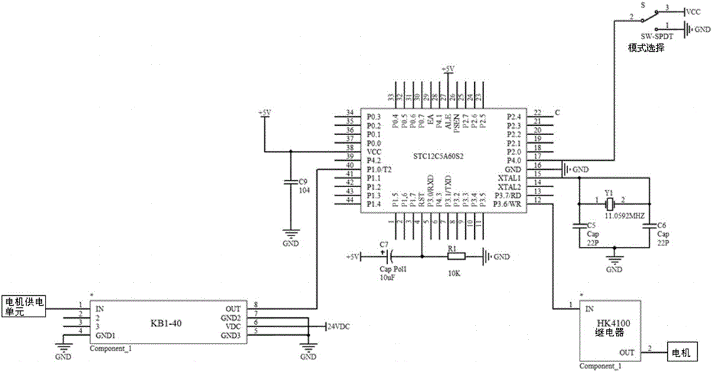
[0022] Such as figure 1 As shown, the present embodiment provides a conveyor belt tear-resistant monitoring system, including STC12C5A60S2 single-chip microcomputer, storage unit, KB1-40 current-voltage converter, HK4100 relay, motor power supply unit, motor and voice alarm, STC12C5A60S2 single-chip microcomputer and storage Unit, KB1-40 current-voltage converter, HK4100 relay and voice alarm signal connection, KB1-40 current-voltage converter is electrically connected to the motor power supply unit, HK4100 relay is connected to the motor signal, and the motor is connected to the conveyor belt power. Specifically, the first pin P1.0 / T2 of the STC12C5A60S2 single-chip microcomputer is connected to the motor power supply unit through the KB1-40 current-voltage converter, the second pin P3.6 / WR of the STC12C5A60S2 single-chip microcomputer is connected to the motor through the HK4100 relay, and the first pin of the STC12C5A60S2 single-chip microcomputer The three-pin P4.0 is conn...
Embodiment 2
[0024] The difference between this embodiment and Embodiment 1 is that the conveyor belt tear prevention monitoring system also includes a flashing light, which is connected to the signal of the STC12C5A60S2 single-chip microcomputer. During the normal operation of the conveyor belt, the flashing light is off or always on. When the single-chip microcomputer controls the motor to stop working through the HK4100 relay, the flashing light keeps flashing to visually notify the operator.
Embodiment 3
[0026] The difference between this embodiment and Embodiment 1 is that the conveyor belt anti-tear monitoring system also includes a display screen, which is connected to the signal of the STC12C5A60S2 single-chip microcomputer, and the display screen is used to display the operating status of the conveyor belt anti-tear monitoring system for convenience. Operators operate, inspect and maintain. The STC12C5A60S2 MCU detects that the current fluctuation of the motor power supply unit in the working mode exceeds the data of the current fluctuation of the motor power supply unit recorded in the learning mode. When the STC12C5A60S2 MCU controls the motor to stop working through the HK4100 relay, the STC12C5A60S2 MCU sends a signal to the display screen. The signal is transmitted to the computer, and the operator observes the display screen to confirm the operation data information of the conveyor belt tear prevention monitoring system.
PUM
 Abstract
Description
Claims
Application Information
 - R&D Engineer
- R&D Manager
- IP Professional
- Industry Leading Data Capabilities
- Powerful AI technology
- Patent DNA Extraction
Browse by: Latest US Patents, China's latest patents, Technical Efficacy Thesaurus, Application Domain, Technology Topic.
© 2024 PatSnap. All rights reserved.Legal|Privacy policy|Modern Slavery Act Transparency Statement|Sitemap