
Textile machine

A mechanical and fiber technology, applied in spinning machines, open-end spinning machines, spinning machines with continuous winding, etc., can solve the problems of inability to locate packages and difficulty in capturing yarn ends.

Active Publication Date: 2016-10-26
MURATA MASCH LTD
View PDF9 Cites 4 Cited by
  • Summary
  • Abstract
  • Description
  • Claims
  • Application Information

AI Technical Summary

Problems solved by technology

[0005] However, in the structure of Japanese Patent Laid-Open No. 2010-189083, since the hardness of the package is different, there is an influence of deformation of the package at the contact portion between the package and the package plate, and the package cannot be positioned accurately.
Moreover, in the above-mentioned structure, even if the surface of the package is positioned, the positional relationship between the suction nozzle and the surface of the package is not directly adjusted, so there is a situation where the positional relationship between the surface of the package and the suction nozzle cannot be adapted to the catching operation. In cases where it is difficult to securely catch the yarn end

Method used


Image

  • Textile machine
  • Textile machine
  • Textile machine

Examples


Embodiment Construction

[0040] Next, a spinning frame (spinning machine) according to an embodiment of the present invention will be described with reference to the drawings. In addition, in this specification, "upstream" and "downstream" mean upstream and downstream in the traveling direction of the yarn during spinning.

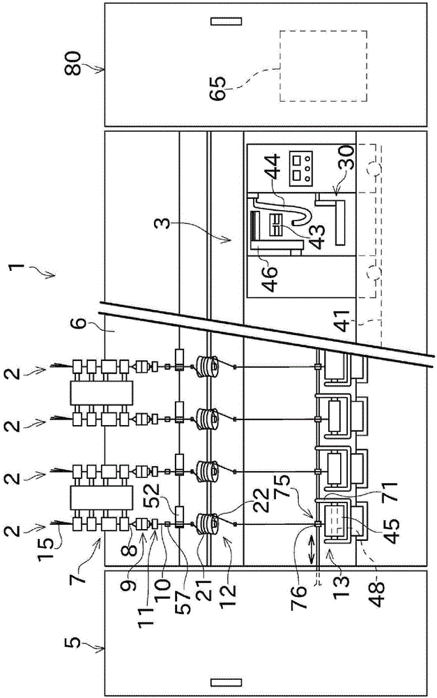
[0041] figure 1 The spinning frame 1 shown as an example of a textile machine includes a plurality of spinning units (winding units) 2 arranged in a row. The spinning frame 1 has a piecing cart (work cart) 3 , a blower box 80 and a power box 5 .

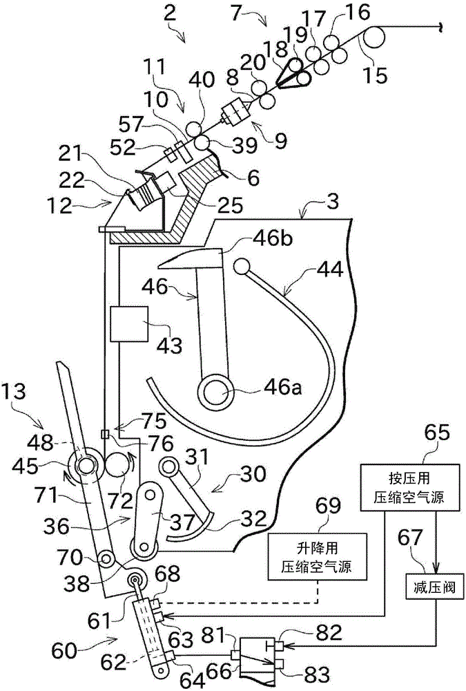
[0042] Such as figure 1 As shown, each spinning unit 2 includes a draft device 7, a spinning device (yarn supply section) 9, a yarn feeding device 11, a yarn slack removing device 12, and a winding device 13 as main structures in order from upstream to downstream.

[0043] The draft device 7 is provided near the upper end of the housing 6 included in the spinning frame 1 . The fiber bundle 8 sent from the drafting device 7 is spun by...


PUM


Abstract

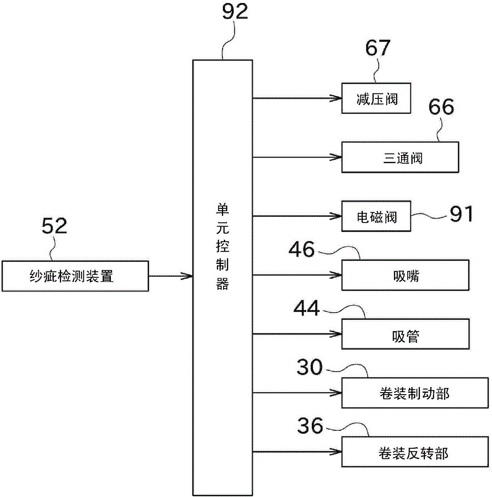
An object is to surely catch a yarn end of a package (45) when performing yarn joining and the like. A suction mouth (46) catches a yarn end of a package (45), a cradle arm (71) rotatably and movably supports the package so as to be movable in a separating direction, and an air cylinder (60) drives the cradle arm to move the package in the separating direction. A unit controller (92) controls, after causing the suction mouth to contact the surface of the package, the air cylinder to move the package in the separating direction. The unit controller provides a control so that the suction mouth catches the yarn end in the state in which the surface of the package and the suction mouth are separated from each other.

Description

technical field [0001] This invention relates to fiber machinery for forming packages. More specifically, it relates to a structure for firmly catching a yarn end of a package during piecing work or the like. Background technique [0002] Conventionally, among fiber machines for forming packages, there are known machines equipped with a structure for catching the yarn end of the package during piecing operation or the like. Japanese Patent Application Laid-Open No. 2010-189083 discloses a spinning frame as such a fiber machine. [0003] The spinning frame disclosed in Japanese Patent Laid-Open No. 2010-189083 includes a suction nozzle, a cradle arm, and a package plate. The suction nozzle catches the yarn end of the package and guides it to the piecing device or the like. The cradle arm rotatably supports the package, and the package can be moved as the cradle arm turns. The package plate comes into contact with the package when the rotation of the package is stopped. ...

Claims


Application Information

Patent Timeline
Patent Type & Authority Applications(China)
IPC IPC(8): D01H15/00D01H4/48
CPCD01H4/48D01H15/00B65H63/0364B65H67/085B65H2701/31
Inventor 目片努
Owner MURATA MASCH LTD
Learn More