Damping piston for combined brake clutch

A technology of braking clutch and damping piston, applied in the direction of fluid drive clutch, non-mechanical drive clutch, clutch, etc., can solve the problems of insignificant positive effect, insufficient stability and reliability, and achieve smooth engagement, sufficient contact and uniform force Effect

Active Publication Date: 2015-09-09
CRRC CHANGZHOU TECH MARK IND CO LTD +1
View PDF7 Cites 0 Cited by
  • Summary
  • Abstract
  • Description
  • Claims
  • Application Information

AI Technical Summary

Problems solved by technology

This technical solution also takes shock absorption into consideration, but for the combined brake clutch, the force on the side of the piston close to the clutch end is different from that on the side close to the brake end. The positive effect of setting a single buffer device for shock absorption is still not obvious, especially the buffer device uses a ring spring, which is not stable and reliable enough for a combined brake clutch with high torque

Method used


Image

  • Damping piston for combined brake clutch
  • Damping piston for combined brake clutch
  • Damping piston for combined brake clutch

Examples


Embodiment 1

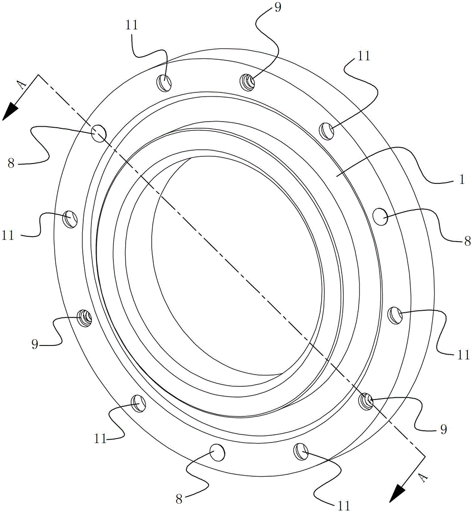
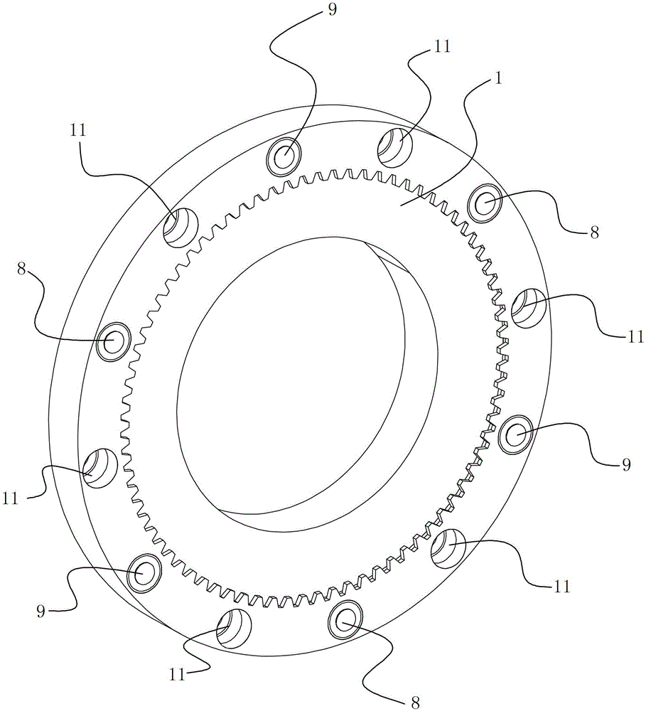
[0035] See Figure 1 to Figure 3, The damping piston for the combined brake clutch of this embodiment includes a piston body 1 , a two-way damping unit 8 and a one-way damping unit 9 . The piston body 1 is provided with 12 through mounting holes 11 equidistantly along the circumferential direction. There are three two-way damping units 8 and three one-way damping units 9 respectively, and the two-way damping units 8 and the one-way damping units 9 are symmetrically installed in the corresponding mounting holes 11 . And the two-way damping units 8 are arranged at equal intervals along the circumferential direction of the piston body 1 . Between the adjacent two-way shock absorbing unit 8 and one-way shock absorbing unit 9, there is an empty mounting hole 11 that does not install two-way shock absorbing unit 8 and one-way shock absorbing unit 9 (in the empty mounting hole 11, two-way shock absorbing unit 8 and one-way shock absorbing unit 9).

[0036] See Figure 6 1. The en...

Embodiment 2

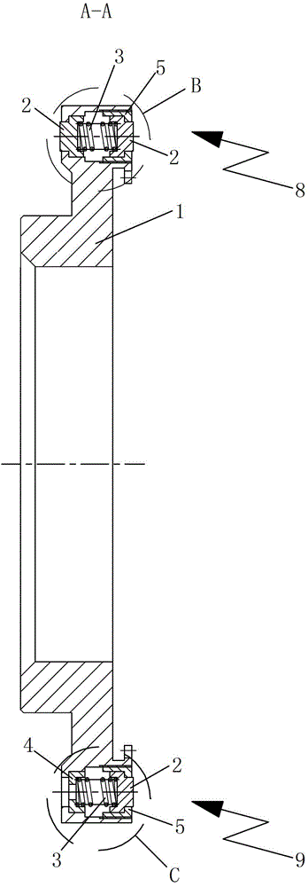
[0043] See Figure 7 , the rest of the damping piston for the combined brake clutch of this embodiment is basically the same as that of Embodiment 1, the difference is that: the end of the mounting hole 11 close to the clutch end is provided with a first annular step 11-1, the mounting hole 11 One end close to the braking end is provided with an internal thread 11-2. The damping concave block 4 of the one-way damping unit 9 is against the second annular step 51, and the protrusion 21 of the damping protrusion 2 of the one-way damping unit 9 passes through the inner circle of the first annular step 11-1 and Extend the piston body 1.

Embodiment 3

[0045] The remainder of the damping piston for the combined brake clutch of this embodiment is basically the same as that of Embodiment 1, except that there are nine mounting holes 11 . There are three two-way damping units 8 and three one-way damping units 9 each, the three two-way damping units 8 are distributed in an equilateral triangle, and the three one-way damping units 9 are also distributed in an equilateral triangle.


PUM


Abstract

The invention relates to a damping piston for a combined type brake clutch. The damping piston comprises a piston body, a plurality of bi-directional damping units and a plurality of single-way damping units, wherein a plurality of penetrating installing holes are formed in the piston body along a circumferential direction at equal intervals; and each bi-directional damping unit and each single-way damping unit are respectively arranged in the corresponding installing hole. According to the damping piston for the combined type braking clutch, according to different force situations of two sides of the piston, stable and reliable damping units are arranged so as to damp the two sides of the piston at different degrees, so that the joint process of the clutch can be smooth and uniform, and the joint noise can be effectively reduced.

Description

technical field [0001] The invention relates to a component of a combined brake clutch, in particular to a piston of a high torque combined brake clutch. Background technique [0002] The combined brake clutch is an important transmission device in the mechanical transmission system, and its main function is to cut off and realize the power transmission with the transmission system. Its working principle is to push the piston to move through the external driving force (air pressure or hydraulic pressure), and to complete the clutch and brake actions through the engagement of the piston and the friction plate set. Due to the compact structure of the combined braking clutch and the coordination and non-interference of clutch and braking actions, it is widely used in forging machinery and other fields. [0003] With the development of combined brake clutches towards larger size, the torque of large combined brake clutches used in special environments is increasing. If the pist...

Claims


Application Information

Patent Timeline
Patent Type & Authority Patents(China)
IPC IPC(8): F16D25/12F16F9/32
Inventor 龚金利周卫兵陈学伟白振清
Owner CRRC CHANGZHOU TECH MARK IND CO LTD
Why Eureka
Try Eureka