Device and method for automatically penetrating through rubber bar

A rubber rod and automatic threading technology, which is applied in the direction of erecting/assembling bridges, auxiliary forming equipment, bridges, etc., can solve the problems of insufficient clamping force of transmission sleeves, insufficient overall driving force, and low work efficiency indicators, achieving a small number, The performance is safe and reliable, and the effect of improving the working environment

Inactive Publication Date: 2016-10-26
朱子毅
View PDF7 Cites 4 Cited by
  • Summary
  • Abstract
  • Description
  • Claims
  • Application Information

AI Technical Summary

Problems solved by technology

[0002] During the construction of prefabricated bridges, rubber tubes can be used to pull out the prestressed tension channels to form holes for subsequent steel strands to be threaded and prestressed. If the rubber tubes are not linearly smooth during installation, the prestressed cause great loss
At present, in the construction of bridge engineering, the installation of prefabricated beam hole hole-forming rubber rods mainly adopts the manual penetration installation method, that is, the hole-forming rubber tubes are manually transported to the two ends of the steel skeleton, guided by one person, and 8 to 10 people are required to manually install the holes. The rubber tube is penetrated into the channel, which has the disadvantages of high labor intensity, low work efficiency index, and the need to build a working platfo

Method used


Image

  • Device and method for automatically penetrating through rubber bar
  • Device and method for automatically penetrating through rubber bar
  • Device and method for automatically penetrating through rubber bar

Examples


Example Embodiment

[0031] The present invention will be described in detail below in conjunction with the accompanying drawings and specific embodiments.

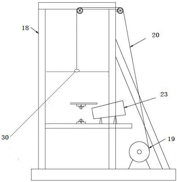
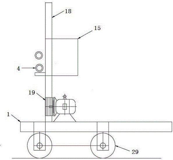
[0032] As shown in the figure, a device for automatically threading rubber rods provided by the present invention includes a support 1, a driving mechanism and a steel chuck 2, including an upper driving wheel 3 and a lower driving wheel 4, and the upper driving wheel 3 and the lower driving wheel 4. The upper and lower driving wheels are opposite and the axial directions are on the same vertical plane. The middle part of the upper driving wheel 3 and the lower driving wheel 4 has a concave arc 5. The two concave arcs are used to accommodate and clamp rubber rods. The driving motor drives the upper driving wheel 3 and the lower drive wheel 4 rotate simultaneously in the opposite direction. The steel chuck 2 is installed at the front end of the rubber rod, and the lower part of the steel chuck 2 is provided with a roller 6 and a telescopic supp...


PUM


Abstract

The invention discloses a device for automatically penetrating through a rubber bar. The device comprises a support seat, a driving mechanism and a steel chuck and is characterized in that the device comprises an upper driving wheel and a lower driving wheel which are opposite up and down, and the axial directions of the upper driving wheel and the lower driving wheel are in the same perpendicular plane; the middles of the upper driving wheel and the lower driving wheel are each provided with a concave arc, the up-down opposite concave arcs are used for containing and clamping the rubber bar, and driving motors drive the upper driving wheel and the lower driving wheel to rotate simultaneously in the opposite directions; and the labor intensity can be relieved, side slipping-off is prevented, and driving is powerful.

Description

technical field [0001] The invention belongs to the technical field of prefabricated bridge construction equipment, in particular to a device for automatically threading rubber rods. Background technique [0002] During the construction of prefabricated bridges, rubber tubes can be used to pull out the prestressed tension channels to form holes for subsequent steel strands to be threaded and prestressed. If the rubber tubes are not linearly smooth during installation, the prestressed cause great loss. At present, in the construction of bridge engineering, the installation of prefabricated beam hole hole-forming rubber rods mainly adopts the manual penetration installation method, that is, the hole-forming rubber tubes are manually transported to the two ends of the steel skeleton, guided by one person, and 8 to 10 people are required to manually install the holes. The rubber tube is penetrated into the channel, and this method has the disadvantages of high labor intensity, ...

Claims


Application Information

Patent Timeline
IPC IPC(8): E01D21/00B28B17/00
CPCE01D21/00B28B17/00
Inventor 朱子毅
Owner 朱子毅
Why Eureka
Try Eureka