
A lock structure applied in shock and vibration scene

A technology for scene application and lock structure, applied in the direction of building lock, building structure, construction, etc., can solve the problems of increased cost, complicated switch, etc., and achieve the effect of convenient operation, simple structure positioning and limit method, and easy maintenance.

Active Publication Date: 2018-08-31
江苏经纬轨道交通设备有限公司
View PDF6 Cites 0 Cited by
  • Summary
  • Abstract
  • Description
  • Claims
  • Application Information

AI Technical Summary

Problems solved by technology

In this way, the cost is significantly increased, and the switch is more complicated, and a special key is required

Method used


Image

  • A lock structure applied in shock and vibration scene
  • A lock structure applied in shock and vibration scene
  • A lock structure applied in shock and vibration scene

Examples


Embodiment Construction

[0014] The preferred embodiments of the present invention will be described in detail below in conjunction with the accompanying drawings, so that the advantages and features of the present invention can be more easily understood by those skilled in the art, so as to define the protection scope of the present invention more clearly.

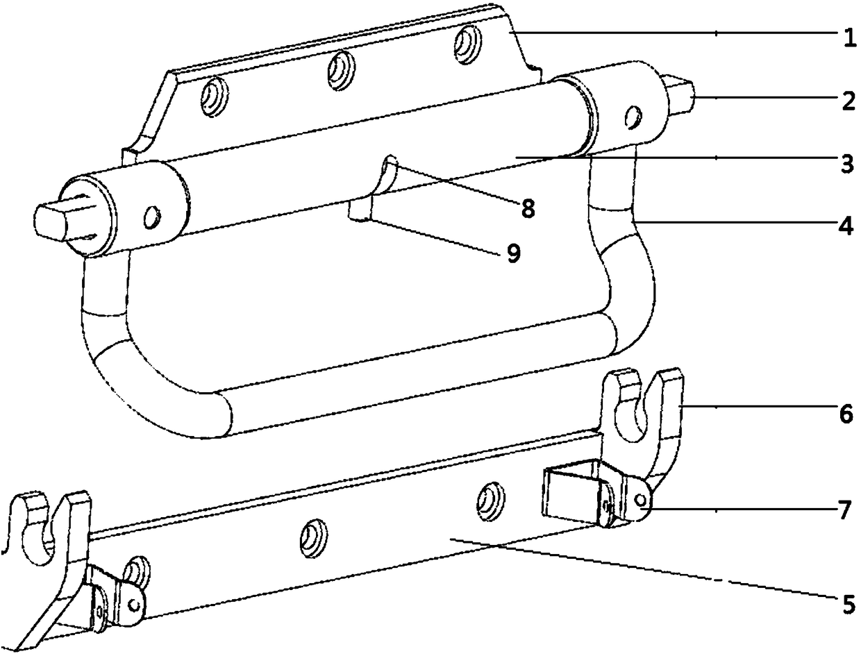
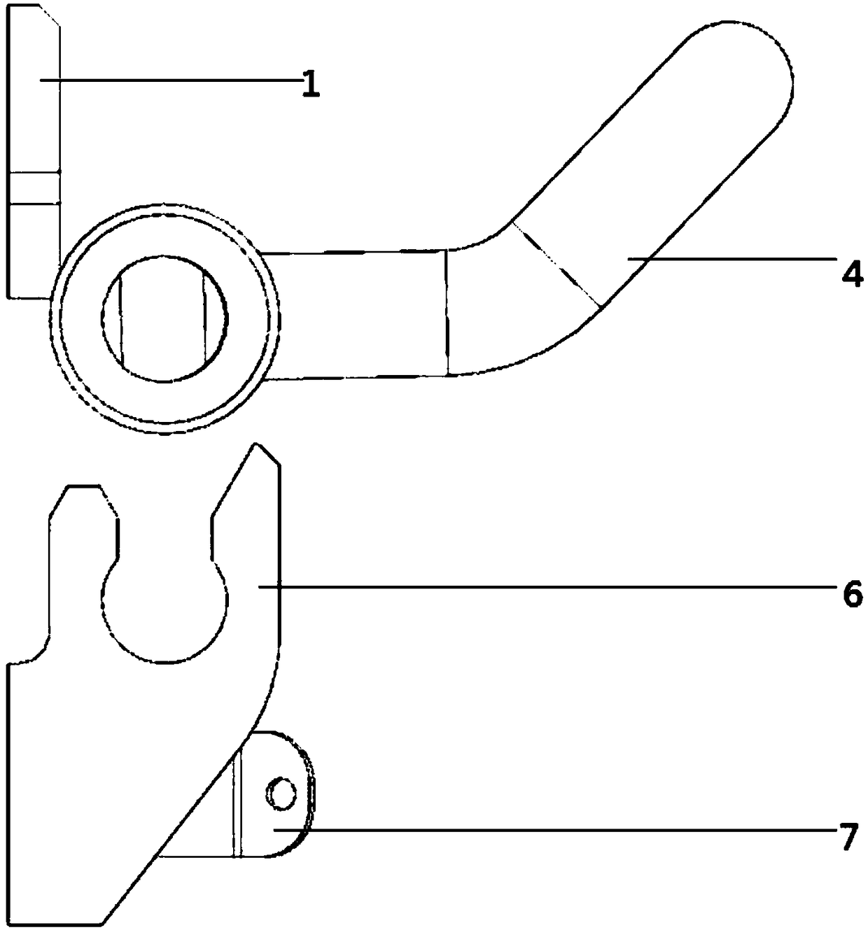
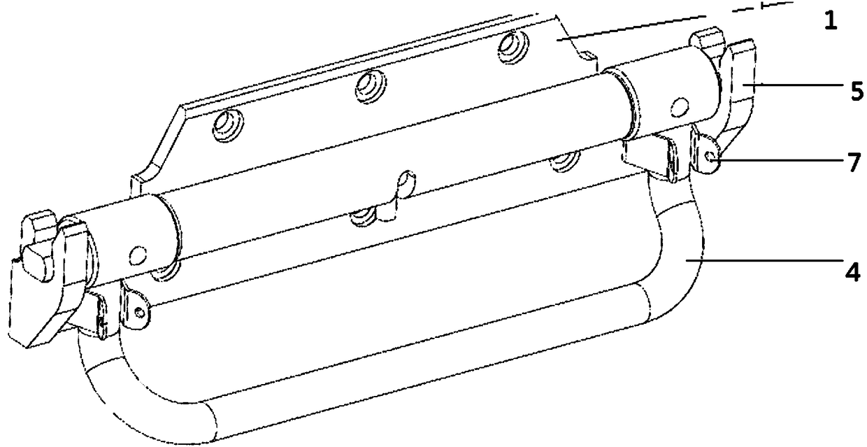
[0015] Please refer to the attached figure 1 , figure 2 and image 3 , the embodiment of the present invention includes: a fixed part, a rotating part and an up and down movable part; the fixed part includes a lower cover plate 5, a lock 7 and a lock groove 6; the rotating part includes a lock head 2, a lock handle 4 and Limit pin 9; the upper and lower movable parts include an upper cover plate 1 and a connecting shaft 3; the upper cover plate 1 is connected to the connecting shaft 3; a sleeve is fixed at both ends of the lock handle 4; the sleeve covers On the connecting shaft 3; the lock head 2 passes through the inside of the connecting sh...


PUM


Abstract

The invention provides a lockset structure applied to an impact vibration scene. The lockset structure applied to the impact vibration scene comprises a fixing portion, a rotational movement portion and an up-and-down movement portion. The fixing portion comprises a lower cover, lock catches and lock slots. The rotational movement portion comprises lock bolt ends, a lock handle and a limiting pin. The up-and-down movement portion comprises an upper cover plate and a connecting shaft. The upper cover plate is connected to the connecting shaft. The two ends of the lock handle are each fixedly provided with a sleeve. The connecting shaft is sleeved with the sleeves. The lock bolt ends are fixedly installed on the sleeves. The two ends of the lower cover plate are each provided with one lock catch. The lower cover plate is provided with two lock slots matched with the lock handle. The lockset structure applied to the impact vibration scene is simple, convenient to install and easy to manufacture, and all-dimensional locking is achieved through a simple structure locating manner and a simple limiting manner; and besides, a key is not needed, and the lockset structure applied to the impact vibration scene is convenient to operate and maintain.

Description

technical field [0001] The invention relates to the field of door locks, in particular to a lock structure applied in shock and vibration scenarios. Background technique [0002] There are many kinds of door locks now, most of which have keys, and some locks only play the role of handles. At present, most of the door lock structures used in shock and vibration scenarios are single-point locks, and many of them are used together and locked by a key. This obviously increases the cost greatly, and the switch is relatively complicated, and needs to be equipped with a special key. In view of this, it is necessary to provide a new type of fast keyless lock structure involving applications in shock and vibration scenarios. Contents of the invention [0003] The main technical problem to be solved by the present invention is to provide a lock structure applied in a shock vibration scene, which has a reasonable design and a simple structure, and solves the problem that a key need...

Claims


Application Information

Patent Timeline
Patent Type & Authority Patents(China)
IPC IPC(8): E05B17/00
CPCE05B17/00
Inventor 刘巍
Owner 江苏经纬轨道交通设备有限公司
Learn More