A Drilling Tool Using Turbine to Realize Rotating Impact

A technology for drilling tools and turbine rotors, which is applied to drilling equipment, driving devices for drilling in wellbore, earth-moving drilling, etc. Improve energy utilization and ensure the effect of effective transmission

Active Publication Date: 2018-06-01
沛县金瑞机械制造有限公司
View PDF6 Cites 0 Cited by
  • Summary
  • Abstract
  • Description
  • Claims
  • Application Information

AI Technical Summary

Problems solved by technology

[0005] In order to solve the problems of the unsatisfactory use effect of the existing hydraulic impactor and the low rock-breaking efficiency of the drill bit, the present invention provides a downhole tool that utilizes a turbine to achieve rotary impact

Method used


Image

  • A Drilling Tool Using Turbine to Realize Rotating Impact
  • A Drilling Tool Using Turbine to Realize Rotating Impact
  • A Drilling Tool Using Turbine to Realize Rotating Impact

Examples


Embodiment Construction

[0013] The present invention will be further described below in conjunction with accompanying drawing:

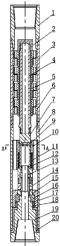
[0014] See attached figure 1 , a drilling tool that uses a turbine to achieve rotary impact, consisting of an upper joint 1, a nut 2, an upper casing 3, a turbine shaft 4, a turbine rotor 5, a turbine stator 6, a central tube 7, a lower casing 8, and a sleeve seal Ring 9, sleeve 10, disc spring 11, piston sealing ring 12, piston 13, hammer 14, clamping sleeve sealing ring 15, half ring 16, clamping sleeve 17, O-ring sealing ring 18, anvil 19 and Bafang The sleeve 20 is composed of the upper joint 1, the upper casing 3 and the lower casing 8, which are threaded in sequence, and after being fixed, a cavity is formed inside, and the cavity is followed by a nut 2, a turbine shaft 4, and a center Pipe 7, hammer 14, anvil 19; the upper end of the turbine shaft 4 is threadedly connected with the nut 2, and the lower end is threadedly connected with the center pipe 7; the turbine ...


PUM


Abstract

The invention relates to a drilling tool for achieving rotating impact through a turbine in the field of petroleum drilling. The drilling tool can convert pressure energy of mud into rotating impact of an impact hammer. According to the technical scheme, an upper joint, an upper shell and a lower shell are matched through threads in sequence and are fixed to form a cavity inside, and a nut, a turbine shaft, a central pipe, the impact hammer and an anvil block are sequentially located in the cavity from top to bottom; the upper end of the turbine shaft is connected with the nut through threads, and the lower end of the turbine shaft is connected with the central pipe through threads; a turbine rotor is in spline fit with the turbine shaft; six through holes are evenly distributed in the circumferential direction of the central pipe, and the lower end of the central pipe is connected with the impact hammer through threads; a sleeve is connected with the lower shell through threads; a disc spring is clamped in the middle through the shaft shoulder of a sleeve and the shaft shoulder of the central pipe; the lower end face of the impact hammer is provided with a rectangular water passing channel and matched with the end face of the anvil block; and a piston is connected with the anvil block through threads, and symmetrical ventilation holes are formed in the circumferential direction of the shaft shoulder of the piston. The drilling tool can generate periodical rotating impact on a lower drilling rig, effectively improve the rock breaking efficiency of a drill and reduce drilling cost.

Description

technical field [0001] The invention relates to a drilling tool for oil and gas drilling, geological drilling and other fields, which utilizes a turbine to realize rotary impact. Background technique [0002] With the continuous increase of oil consumption, shallow oil fields can no longer meet the needs of human beings, and oil extraction is developing in the direction of deep wells and ultra-deep wells with large oil reserves, complex geology and difficult drilling. What conventional drilling mainly adopts now is to utilize the rotary table to drive the drill string to rotate the drill bit to break the drilling method (rotary drilling) of the rock at the bottom of the hole. However, when drilling deep and ultra-deep wells, the rock is often hard and the working conditions are complicated. Using traditional methods often leads to problems such as low rock-breaking efficiency of the drill bit and a decrease in the mechanical speed of penetration. [0003] At present, impact...

Claims


Application Information

Patent Timeline
Patent Type & Authority Patents(China)
IPC IPC(8): E21B4/16
CPCE21B4/16
Inventor 田家林杨志杨琳吴波吴纯明刘刚袁长福
Owner 沛县金瑞机械制造有限公司
Why Eureka
Try Eureka