
Clamp ring structure

A snap ring and fastening bolt technology, which is applied in the direction of pipes/pipe joints/fittings, hose connection devices, mechanical equipment, etc., can solve the problems of time-consuming and labor-intensive tying process, pulling out holes, and easy loosening of tying knots. The operation, the effect is ideal, and the effect of binding is firm

Inactive Publication Date: 2016-10-26
新昌县羽林街道君博机械厂
View PDF0 Cites 1 Cited by
  • Summary
  • Abstract
  • Description
  • Claims
  • Application Information

AI Technical Summary

Problems solved by technology

However, in the existing method of tying the knot with iron wire, since both ends of the iron wire are free ends, it is not easy to fix, and it is easy to loosen when tying the knot.
When the air pressure inside the steel pipe is high, this way of tying is prone to leakage, leaking, and hole pulling accidents, which will lead to gas alarms
In severe cases, it may even affect the safety of passing personnel
Moreover, when iron wire is used for tying, the tying process is time-consuming and laborious
When it is temporarily tied, the iron wire cannot be reused after being tied once, and the loss is large
When the binding time is long, the iron wire is easy to rust or even break, which will also lead to many unsafe effects including the above
Therefore, the effect of adopting iron wire binding in the prior art is very unsatisfactory

Method used


Image

  • Clamp ring structure
  • Clamp ring structure

Examples


Embodiment Construction

[0010] Below in conjunction with accompanying drawing, the present invention will be further described:

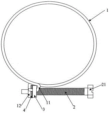
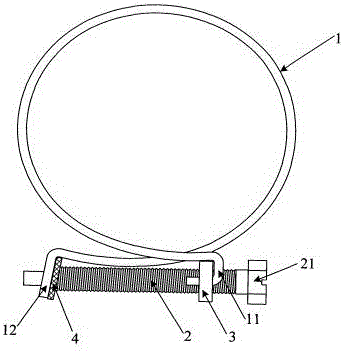
[0011] As shown in Figure 1, the fastening plate 3 is connected to the fastening bolt 2 by a screw. The threaded connection described here means that the fastening plate 3 is embedded with a second thread that matches the first thread on the fastening bolt 2, so that the fastening plate 3 relies on the first thread on it. The two threads can move helically on the fastening bolt 2 along the first thread. Washer 4 is also attached to fastening bolt 2. However, the fastening plate 3 is located between the washer 4 and the head 21 of the fastening bolt 2 . The hoop 1 is an open ring structure surrounded by elastic steel wire material. The hoop 1 includes two connecting ends: a first connecting end 11 and a second connecting end 12. The first connection end 11 and the second connection end 12 are connected to the fastening plate 3 and the gasket 4 respectively after interse...


PUM


Abstract

The invention relates to a clamp ring structure which is characterized by comprising a fastening bolt, a fastening plate and an unclosed circular hoop. The fastening plate is connected with the fastening bolt by screw threads; a gasket is further connected onto the fastening bolt, and the fastening plate is positioned between the gasket and the head of the fastening bolt; the circular hoop is enclosed by an elastic steel wire; a first connecting end and a second connecting end of the circular hoop cross each other and then are respectively connected with the fastening plate and the gasket; the first connecting end and the second connecting end are two free ends of the elastic steel wire, or the first connecting end is a combination of the two free ends of the elastic steel wire. The clamp ring structure has the advantages that the two connecting ends of the circular hoop are respectively connected to the fastening plate and the gasket in a crossing manner, the fastening plate on the fastening bolt can rotate, accordingly, the distance from the fastening plate to the gasket can be prolonged, the diameter of an unclosed circular ring enclosed by the circular hoop can be diminished, and effects of tightly tying hoses on steel pipes can be realized.

Description

technical field [0001] The invention relates to a snap ring structure. Background technique [0002] In the underground construction process of coal mines, it is more common to softly connect the hose to the steel pipe by tying. Especially in the drainage systems such as drilling stubble, upper corner pipe connection on the mining surface, etc., it is essential to use. In the prior art, to connect the hose to the steel pipe, one end of the hose is usually sleeved on the port at one end of the steel pipe. This connection mode is the soft connection mentioned above. Usually, in order to ensure the effect of the soft connection, iron wires are used to tie the hose to fix the hose sleeved outside the steel pipe to ensure that it will not slip. But, existing this mode that adopts iron wire to tie a knot, because iron wire two ends are free ends, it is not easy to fix, and it is easy to loosen when tied. When the air pressure in the steel pipe is high, this kind of knotting me...

Claims


Application Information

Patent Timeline
Patent Type & Authority Applications(China)
IPC IPC(8): F16L33/02
CPCF16L33/02
Inventor 蒋文炯
Owner 新昌县羽林街道君博机械厂
Learn More