
One-way cyclic starting structure of novel oscillation type heat conduction device

A one-way circulation, oscillating technology, used in indirect heat exchangers, lighting and heating equipment, etc., can solve problems such as limited starting force, difficulty in achieving one-way circulation of working fluid, and inability to achieve

Inactive Publication Date: 2016-10-26
SUZHOU FORCECON ELECTRIC
View PDF6 Cites 0 Cited by
  • Summary
  • Abstract
  • Description
  • Claims
  • Application Information

AI Technical Summary

Problems solved by technology

[0004] However, the use experience of traditional oscillating heat pipes has found that the starting force of the internal working fluid to generate circulation is still quite limited, because in the structural design of existing oscillating heat pipes, pressure differences are usually generated by differences in pipe diameters to achieve The purpose of starting gas circulation in one direction, but this existing form has been found in actual use experience. When the working fluid corresponding to the heat source inside the heat pipe begins to be heated and evaporated to generate thrust, due to its passage to the large diameter and small The working fluid of the pipe diameter is in a smooth flow state, so the average pressure of the two flow directions often cancels out at a junction, and it is impossible or difficult to achieve the expected purpose of starting the one-way circulation of the working fluid. This is really necessary. Thinking about important technical issues for breakthroughs

Method used


Image

  • One-way cyclic starting structure of novel oscillation type heat conduction device
  • One-way cyclic starting structure of novel oscillation type heat conduction device
  • One-way cyclic starting structure of novel oscillation type heat conduction device

Examples


Embodiment

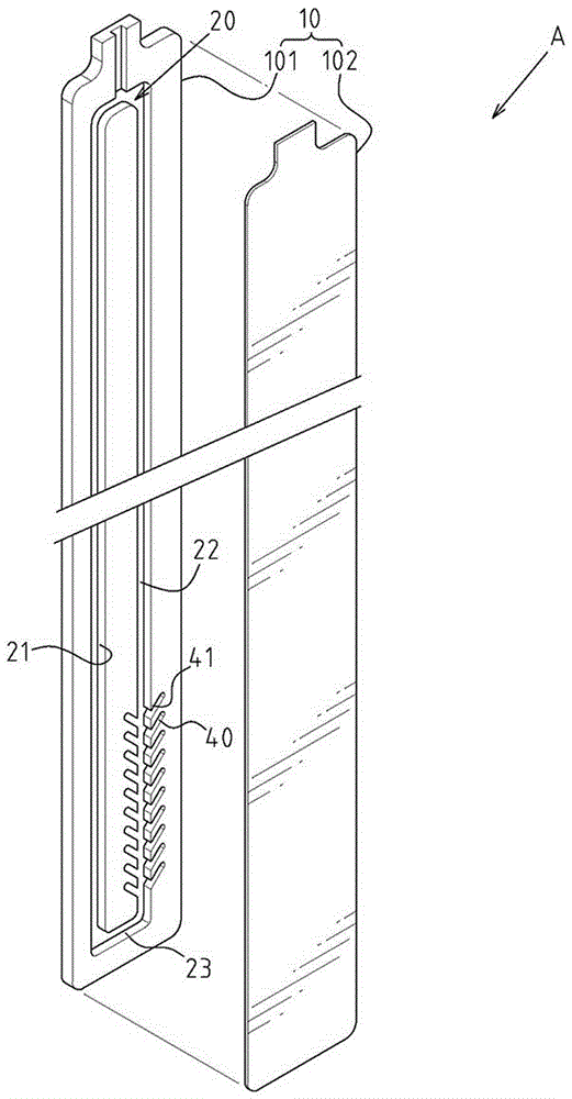
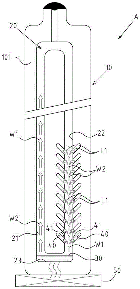
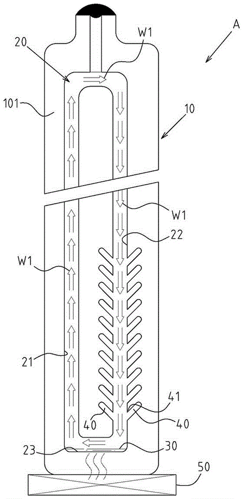
[0024] Example: see Figure 1~4 Shown is a preferred embodiment of the one-way cycle start-up structure of the novel oscillating heat conduction device of the present invention, but these embodiments are for illustration purposes only, and are not limited by this structure in patent application.

[0025] The oscillating heat conduction device A includes a casing 10 and a loop-type flow channel 20 inside the casing 10. The loop-type flow channel 20 includes a heated section 23 and a first side guide section 21. And a second side guide section 22, and a working fluid 30 is placed in the loop-type flow channel 20, and the working fluid 30 in the heated section 23 evaporates to form a vapor pressure to push the working fluid 30 to flow; and wherein, the first At least one side of the two-side guide section 22 is provided with at least one fork-shaped spoiler 40 protruding sideways in the form of a blind hole, between the fork-shaped spoiler 40 and the second side guide section 22 ...


PUM


Abstract

The invention provides a one-way cyclic starting structure of a novel oscillation type heat conduction device. A loop type runner is arranged in a shell of the oscillation type heat conduction device and comprises a heated area segment, a first side flow guiding area segment and a second side flow guiding area segment; work liquid is contained in the loop type runner; the work liquid in the heated area segment evaporates to form steam pressure so that the work liquid can be pushed to flow; at least one side of the second side flow guiding area segment is provided with a fork-shaped flow resisting channel protruding towards the side and being in a blind hole shape; an inverted-fork edge part is formed between the fork-shaped flow resisting channel and the second side flow guiding area segment; the protruding and extending direction of the inverted-fork edge part is opposite to the flowing direction of the work liquid coming from the heated area segment; and thus, the fork-shaped flow resisting channel is used for blocking the work liquid moving towards the second side flow guiding area segment from the heated area segment and relatively promoting the flowing state of the work liquid moving towards the first side flow guiding area segment from the heated area segment, and achievement of the one-way cyclic starting state of the work liquid is accelerated.

Description

technical field [0001] The invention relates to a heat conduction device; in particular, it refers to an innovative form of a one-way cycle starting structure of an oscillating heat conduction device. Background technique [0002] Heat conduction devices such as heat pipes or heat plates have been widely used as heat dissipation structures for various electronic products in recent years due to their good heat transfer performance. Especially in computer structures, most heat pipes can be seen in the configuration. [0003] In view of the problems and shortcomings that the traditional heat pipe structure is still too complicated, a related industry subsequently developed an oscillating heat pipe without a capillary structure. The overall structure of the oscillating heat pipe is quite simple, and it is usually connected by a smooth thin tube. And its driving force is the capillary force generated by the smaller pipe diameter, the gravity of the working fluid and the bubble pr...

Claims


Application Information

Patent Timeline
IPC IPC(8): F28D15/02
CPCF28D15/0233
Inventor 何信威黄志仁叶肇皓
Owner SUZHOU FORCECON ELECTRIC
Learn More