Eureka AIR delivers breakthrough ideas for toughest innovation challenges, trusted by R&D personnel around the world.

Infrared spectroradiometer based on light splitting of gradual filter

A technology of gradient filtering and infrared spectroscopy, which is applied in the field of infrared spectroradiometers based on gradient filter spectroscopy, can solve the problems of inability to control the field of view of the instrument, difficulty in ensuring the focus position of the variable diaphragm, and increasing the difficulty of production and installation, etc. problem, to achieve the effect of ensuring the field of view control effect, ensuring the detection energy intensity, and simple installation and adjustment

Inactive Publication Date: 2016-10-26
THE 41ST INST OF CHINA ELECTRONICS TECH GRP
View PDF13 Cites 6 Cited by
  • Summary
  • Abstract
  • Description
  • Claims
  • Application Information

AI Technical Summary

Problems solved by technology

[0004] (1) Focus twice at the gradient filter and the detector. Since the gradient filter and the iris itself have a certain thickness, plus the fixture and the motor fixing device, the distance between the iris and the iris There is inevitably a certain distance between the front and back, and it is difficult to ensure that the iris is at the focus position. However, in practical applications, the control of the iris to the field of view requires that it be at the focus as much as possible. Therefore, this structure cannot achieve a good field of view of the instrument. control
(2) The focus is reflective. Compared with the lens, the influence of the surface accuracy of the reflector on the optical path is double. The precision required for the surface of the reflector is greatly improved, which increases the difficulty of production and adjustment.

Method used


Image

  • Infrared spectroradiometer based on light splitting of gradual filter
  • Infrared spectroradiometer based on light splitting of gradual filter

Examples


Embodiment Construction

[0014] The present invention provides an infrared spectroradiometer based on gradient filter spectroscopy. In order to make the purpose, technical solution and effect of the present invention clearer and clearer, the present invention will be further described in detail below. It should be understood that the specific embodiments described here are only used to explain the present invention, not to limit the present invention.

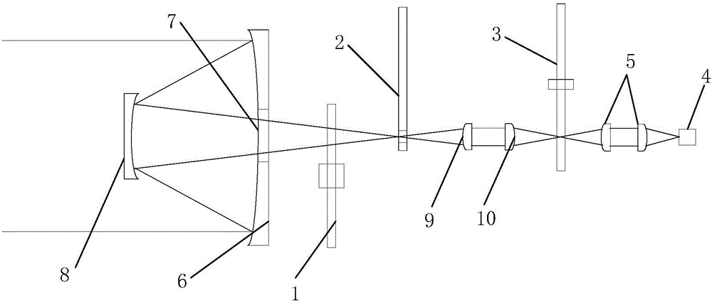
[0015] The invention provides a kind of infrared spectroradiometer based on gradient filter spectroscopic, such as figure 2 As shown, it includes an incident lens, wherein a light chopper 1 is arranged at the rear of the incident lens, an iris diaphragm 2 is arranged behind the light chopper 1, and a gradient filter 3 is arranged behind the iris diaphragm 2, which can A first focusing lens group is arranged between the iris diaphragm 2 and the gradient filter 3, an infrared detector 4 is arranged behind the gradient filter 3, and a second focusing len...


PUM


Abstract

The invention discloses an infrared spectroradiometer based on light splitting of a gradual filter. A light chopper is arranged behind an incident lens. A variable diaphragm is arranged behind the light chopper. The gradual filter is arranged behind the variable diaphragm. A first focusing lens group is arranged between the variable diaphragm and the gradual filter. An infrared detector is arranged behind the gradual filter. A second focusing lens group is arranged between the gradual filter and the infrared detector. Light form the incident lens forms a first focusing point by the light chopper, the variable diaphragm is arranged at the first focusing point, the light passes through the variable diaphragm and forms a second focusing point through the first focusing lens group, the gradual filter is arranged at the second focusing point, the light passes through the gradual filter and forms a third focusing point through the second focusing lens group, the infrared detector is arranged at the third focusing point, and the first focusing point, the second focusing point and the third focusing point are arranged on the same axis. According to the invention, the visual field control effect of the variable diaphragm is ensured, the assembling and adjusting difficulty is lowered, and the focusing effect is improved.

Description

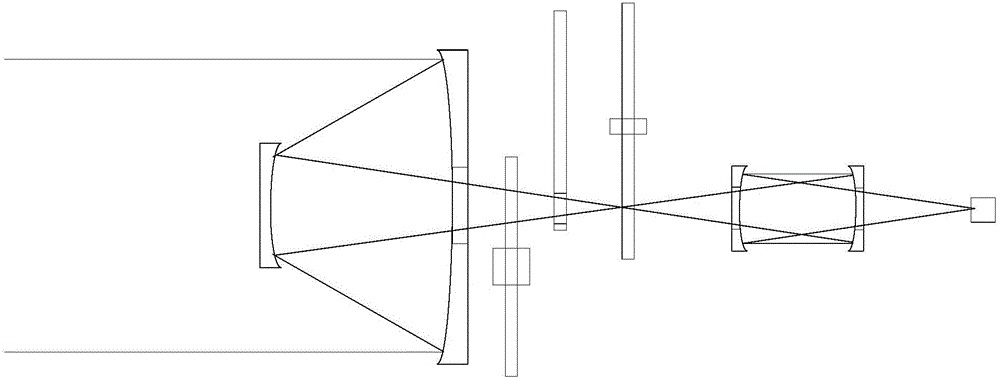
technical field [0001] The invention relates to the field of infrared spectroradiometers, in particular to an infrared spectroradiometer based on gradient filter spectroscopy. Background technique [0002] Infrared spectroradiometers are used for spectroscopic testing of target infrared radiation. The spectroscopic methods include interference spectroscopic methods, grating spectroscopic methods, gradient filter spectroscopic methods, etc. Infrared spectroradiometers based on different spectroscopic methods have their own characteristics. Among them, the gradient filter light splitting method has simple structure, good environmental adaptability and fast test speed. [0003] The traditional infrared spectroradiometer based on the gradient filter spectroscopic method, such as figure 1 As shown, it includes incident lens, light chopper, iris diaphragm, gradient filter, focusing lens group, detector, etc. The focusing lens group consists of two gold-plated mirrors arranged opp...

Claims


Application Information

Patent Timeline
Patent Type & Authority Applications(China)
IPC IPC(8): G01J3/28
CPCG01J3/28
Inventor 胡德信李立功韩顺利刘磊刘加庆江升李志增吕子敬牛继勇
Owner THE 41ST INST OF CHINA ELECTRONICS TECH GRP
Why Eureka
Eureka Blog
Learn More