
Analog-to-digital signal conversion device of digital oscilloscope

A technology of signal conversion device and digital oscilloscope, applied in the direction of digital variable display, etc., can solve problems such as different conversion rates, wrong timing of trigger signals, inconsistent setting parameters, etc., and achieve the effect of improving accuracy, performance and accuracy

Inactive Publication Date: 2016-10-26
UNIV OF ELECTRONICS SCI & TECH OF CHINA
View PDF10 Cites 2 Cited by
  • Summary
  • Abstract
  • Description
  • Claims
  • Application Information

AI Technical Summary

Problems solved by technology

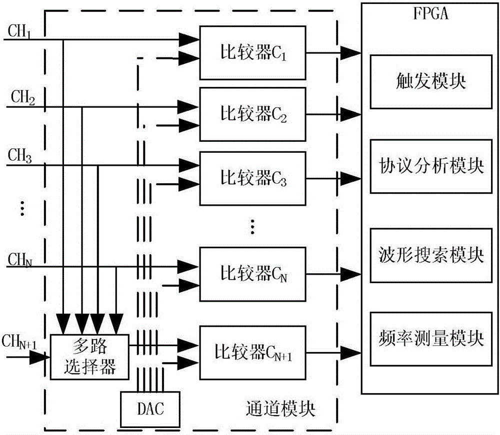
[0005] For example, if the positive slope of channel CH1 is set equal to 20ns to trigger, the existing solution uses one digital signal to be generated by comparator 1, and the other digital signal to be generated by comparator 5 after being selected by a multiplexer, because the conversion rates of the two comparators are different , circuit transmission delay and other issues increase the delay time between the two digital signals, and the delay time is related to the performance of the oscilloscope device, which eventually leads to the timing error of the trigger signal required for acquisition, so the waveform displayed on the screen is different from the actual measured signal. different
[0006] (2) The success rate of high-speed protocol analysis is low
This solution changes the thresholds of the trigger module and the waveform search module, and the oscilloscope does not realize its function according to the parameters given by the user, resulting in that the content displayed on the screen does not match the parameters set by the user.

Method used


Image

  • Analog-to-digital signal conversion device of digital oscilloscope
  • Analog-to-digital signal conversion device of digital oscilloscope
  • Analog-to-digital signal conversion device of digital oscilloscope

Examples


Embodiment

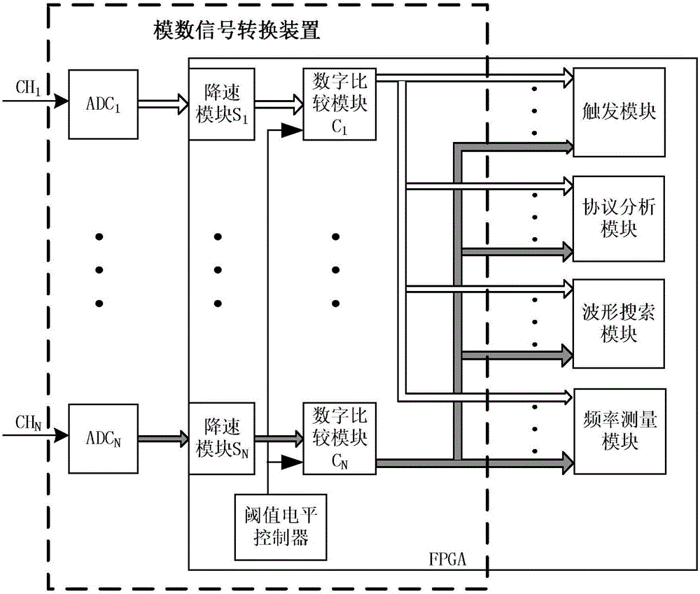
[0030] figure 2 It is a structural diagram of a specific embodiment of the analog-to-digital signal conversion device of the digital oscilloscope of the present invention. Such as figure 2 As shown, the analog-to-digital signal conversion device of the digital oscilloscope of the present invention includes a threshold level controller and N groups of ADC modules ADC i , deceleration module S i and digital comparison module C i , i=1,2,...,N, where the threshold level controller, speed reduction module S i , digital comparison module C i All are realized in FPGA. Each ADC module ADC i , deceleration module S i and digital comparison module C i Corresponds to an input signal channel.

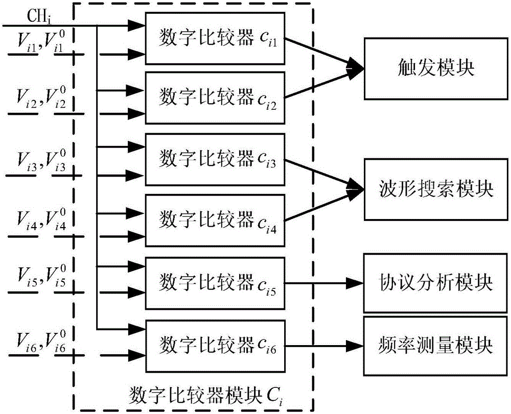
[0031] The threshold level controller is used to generate the threshold level and threshold sensitivity voltage corresponding to each channel in each functional module according to user instructions, where the threshold level is recorded as V ij, the threshold sensitivity voltage is de...


PUM


Abstract

The invention discloses an analog-to-digital signal conversion device of a digital oscilloscope. The analog-to-digital signal conversion device comprises a threshold level controller, N sets of ADC modules, speed reduction modules and digital comparison modules, wherein the threshold level controller, the speed reduction modules and the digital comparison modules are realized in FPGA. Each set of ADC module, speed reduction module and digital comparison module corresponds with one input signal channel. The threshold level controller generates a threshold level and a threshold sensitivity voltage which correspond with each channel in each functional module according to a user instruction and transmits the threshold level and the threshold sensitivity voltage to the corresponding digital comparison module. The ADC module performs analog-to-digital conversion on the input signal of the corresponding channel. The converted signal undergoes speed reduction of the speed reduction module, and then the speed-reduced signal is input into the digital comparison module. The digital comparison module performs determination on the speed-reduced digital signal according to the threshold level and the threshold sensitivity for obtaining a level signal, and then the level signal is input into a corresponding functional module for being processed. The analog-to-digital signal conversion device can independently set the threshold level and the threshold sensitivity for each functional module, thereby improving performance of the digital oscilloscope.

Description

technical field [0001] The invention belongs to the technical field of digital oscilloscopes, and more specifically relates to an analog-to-digital signal conversion device of a digital oscilloscope. Background technique [0002] As a general-purpose test instrument, digital oscilloscopes are widely used in various industries, so it is necessary for the oscilloscope to have multiple functions to meet the needs of various test occasions. In the digital oscilloscopes currently on the market, trigger acquisition, protocol analysis, waveform search, and frequency measurement functions are essential functions of a digital oscilloscope. Make a decision to generate a digital signal, that is, complete the analog-to-digital signal conversion of the input signal. figure 1 It is a structural diagram of an analog-to-digital signal conversion device of a digital oscilloscope in the prior art. Such as figure 1 As shown, at present, most of the domestic use FPGA (Field-Programmable Gate...

Claims


Application Information

Patent Timeline
Patent Type & Authority Applications(China)
IPC IPC(8): G01R13/02
CPCG01R13/02
Inventor 曾浩许波郭连平潘卉青张沁川蒋俊
Owner UNIV OF ELECTRONICS SCI & TECH OF CHINA
Learn More