Drafting arrangement for spinning machine

A drafting device and spinning machine technology, applied in spinning machines, spinning machines with continuous winding, drafting equipment, etc., can solve the problems of not being able to ensure that hollow parts are pressed against rollers, and achieve simple and reliable structure And the effect of uniform compression

Pending Publication Date: 2020-07-31
MASCHINENFABRIK RIETER AG
View PDF3 Cites 0 Cited by
  • Summary
  • Abstract
  • Description
  • Claims
  • Application Information

AI Technical Summary

Problems solved by technology

The disadvantage of this type of device is that a press-fit element alone does not yet ensure a defined pressing of the hollow profile against the rollers

Method used


Image

  • Drafting arrangement for spinning machine
  • Drafting arrangement for spinning machine
  • Drafting arrangement for spinning machine

Examples


Embodiment Construction

[0033] In the following description of the alternative embodiments, the same reference numerals are used for identical and / or at least similar features of technical solution and / or operating principle. If these features are not described in detail again, their technical solutions and / or working principles are equivalent to those of the previously described features.

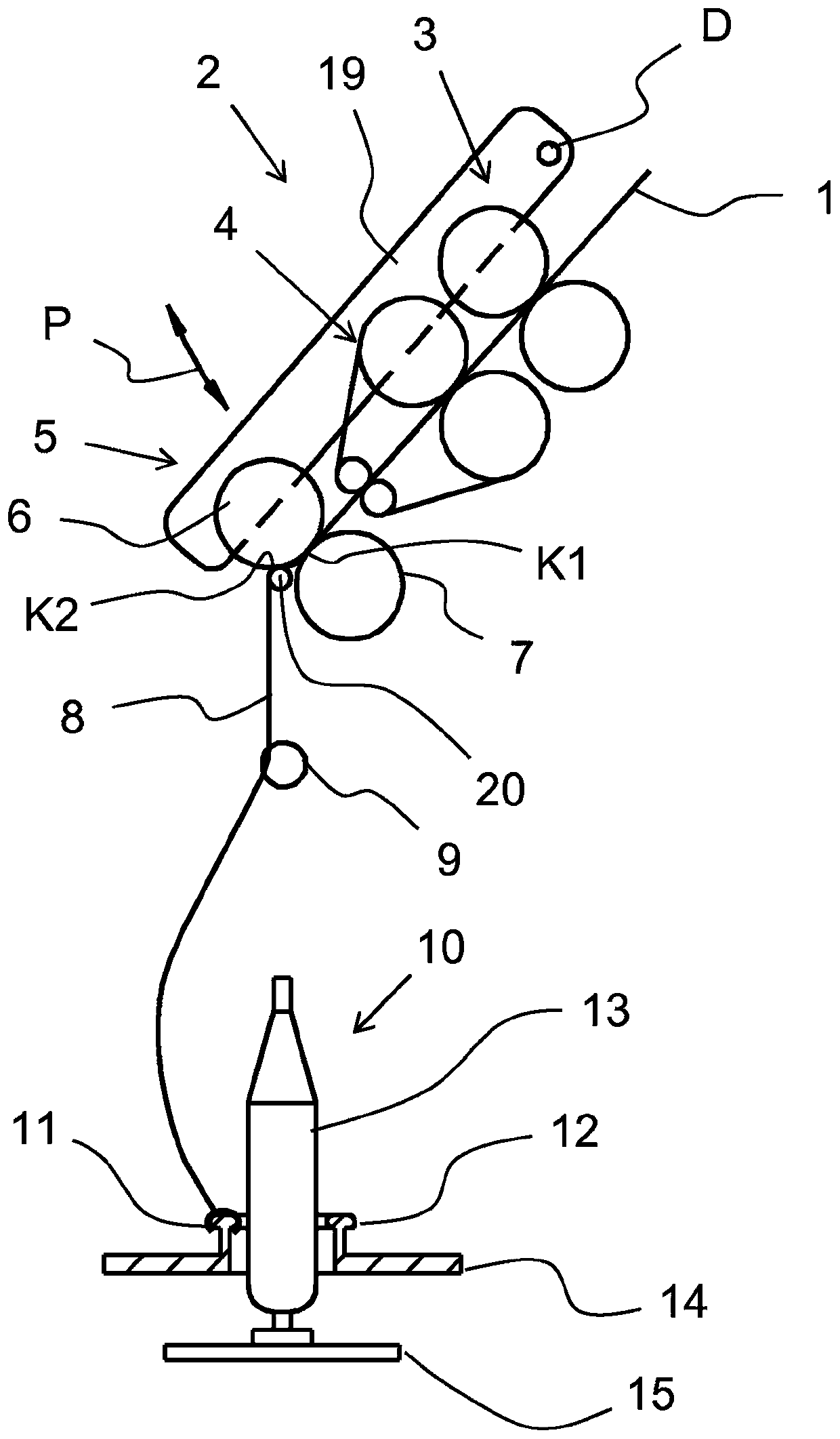
[0034] figure 1 is a schematic diagram of a longitudinal section of a spinning machine, in particular a ring spinning machine with a compression device 20 . Several components of the spinning machine, namely the drafting device 2 and the spinning device 10 are schematically shown in the figure. The drafting device 2 is composed of three roller pairs: an input roller pair 3 , a belt roller pair 4 and an output roller pair 5 . The output roller pair 5 is formed by the output top roller 6 and the output bottom roller 7 . The two rollers of a roller pair come together and form a clamping point at their point of co...


PUM


Abstract

The invention relates to a drafting arrangement for a spinning machine. The drafting arrangement has top and bottom rollers and having a load arm (19) on which the top rollers of the drafting arrangement are arranged, and also has a starting roller pair (5) which is formed by a starting top roller (6) and a starting bottom roller (7), and has a pneumatic compression device (20) downstream of the starting roller pair (5) of the drafting arrangement (2) for sealing a drafted fiber strand (8). The pneumatic compression device has a suction tube (17) to which suction can be applied, wherein the suction tube (17) is entwined by a screen element (18), the pneumatic compression device (20) has a fiber bundling zone (16), and the fiber bundling zone (16) is delimited by two clamping locations (K1,K2), wherein a first clamping location (K1) is defined by the two rollers of the starting roller pair (5), and a second clamping location (K2) is formed by one (6) of the two rollers of the startingroller pair (5) and the screen element (18), wherein the suction tube (17) is arranged on a base holder (25), and the base holder is arranged on the starting top roller (6) and the load arm (19). In the compression device for the drafting arrangement, the suction tube (17) is arranged on the base holder (25) and the base holder has receptacles for fixing to a starting top roller (6) and a load arm(19) of the drafting arrangement.

Description

technical field [0001] The invention relates to a drafting device for a spinning machine, the drafting device has a top roller, a bottom roller, a load arm, on which the top roller of the drafting device is arranged, has an output a pair of rollers consisting of an output top roller and an output bottom roller, and having a pneumatic compression device for compressing the drawn fiber assembly downstream of the output roller pair of the drafting device, the compression device With a suction pipe that can be sucked, wherein the suction pipe is surrounded by a filter element, the compression device has a fiber bundle area and the fiber bundle area is delimited by two clamping points, wherein the first clamping point Defined by the two rollers of the pair of delivery rollers, a second clamping point is formed by one of the two rollers of the pair of delivery rollers and the sieve element. Background technique [0002] A drafting device for a spinning machine comprises at least ...

Claims


Application Information

Patent Timeline
Patent Type & Authority Applications(China)
IPC IPC(8): D01H5/72
CPCD01H1/025D01H5/72
Inventor G·沙夫勒曼弗雷德·鲍尔K·胡贝尔
Owner MASCHINENFABRIK RIETER AG
Why Eureka
Try Eureka