
Perforated current collector foil preparation method and device based on staggered texturing rolling

A current collector and foil technology, applied in the field of electrochemical energy storage, can solve the problems of complex etching process, burrs on the foil surface, and high cost of mass production

Active Publication Date: 2021-05-07
喆烯新材(北京)科技有限公司
View PDF7 Cites 2 Cited by
  • Summary
  • Abstract
  • Description
  • Claims
  • Application Information

AI Technical Summary

Problems solved by technology

However, each method has the following problems: the hole diameter prepared by the punching method is usually above 300 μm, and there are burrs on the surface of the foil. If the size of the punching hole is further reduced, there will be problems in the strength of the punch and the convex needle; the etching method is complicated. The cost of large-scale production is high; the laser drilling method either uses a combination of fixed laser points and guide rails to drill holes, or uses a scanner to drill holes. The drilling with moving guide rails needs to solve the problem of efficiency, while the processing format and aperture of scanning drilling cannot be independent. set up
[0005] On the whole, the existing current collector foil surface texture rolling method and perforation method have defects, and there is no effective integrated surface texture and perforation method and device, which cannot meet the requirements of electrochemical energy storage devices.

Method used

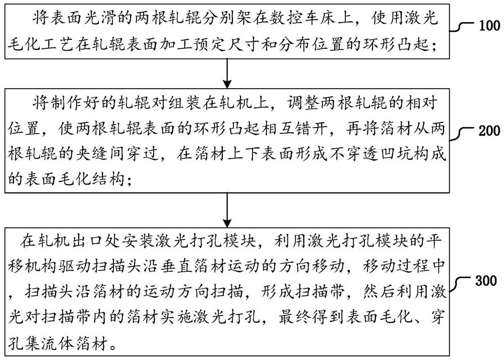
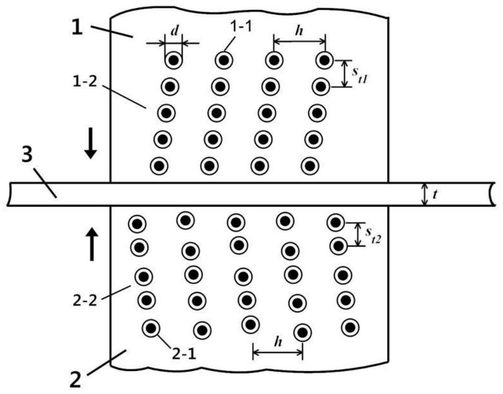
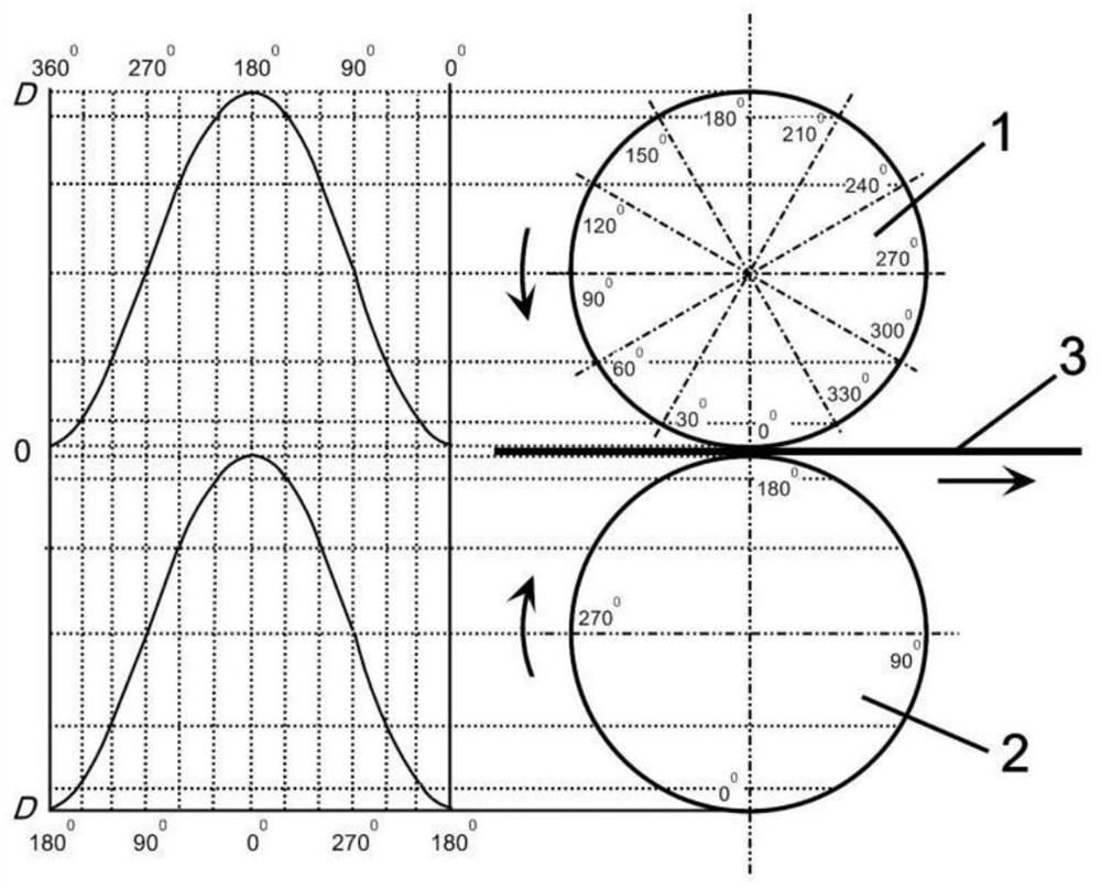

Image

  • Perforated current collector foil preparation method and device based on staggered texturing rolling
  • Perforated current collector foil preparation method and device based on staggered texturing rolling
  • Perforated current collector foil preparation method and device based on staggered texturing rolling

Examples


preparation example Construction

[0022] Such as figure 1 As shown, in one embodiment of the present invention, a method and device for preparing a perforated current collector foil based on dislocation texture rolling are disclosed. The preparation method includes the following steps:

[0023] Step 100, placing two rolls with smooth surfaces on a CNC lathe respectively, and processing ring-shaped protrusions of predetermined size and distribution position on the surface of the rolls using a laser texturing process;

[0024] In this step, the roll pairs are respectively processed along the helical trajectory with the same laser texturing parameters, forming ring-shaped protrusions 1-1 and 2-1 with the same height and diameter on the surfaces of the two rolls 1 and 2, but the two The helical lines on the surfaces of rolls 1 and 2 rotate in opposite directions, such as figure 2 As shown, the circumferential distances between the annular protrusions 1-1 on the surface of one of the rolls 1 are fixed, and the ci...


PUM

PropertyMeasurementUnit
diameteraaaaaaaaaa
thicknessaaaaaaaaaa
pore sizeaaaaaaaaaa

Abstract

The invention discloses a perforated current collector foil preparation method and device based on staggered texturing rolling. The preparation method comprises the steps that firstly, two rollers are respectively erected on a numerical control lathe, and annular protrusions are machined on the surfaces of the rollers; the manufactured roller pairs are assembled on a rolling mill, the annular protrusions on the surfaces of the two rollers are made to be staggered, then foil penetrates through the gap between the two rollers, and rolling force is applied to the upper surface and the lower surface of the foil to form a surface-textured structure formed by non-penetrating pits; and a laser drilling module is installed at an outlet of the rolling mill, a scanning head is driven by a translation mechanism of the laser drilling module to move in the direction perpendicular to the movement direction of the foil, in the moving process, the scanning head scans in the movement direction of the foil to form a scanning belt, laser drilling is conducted on the foil, and finally the surface-textured and perforated current collector foil is obtained. The double-sided pits of the perforated base foil rolled through the method and the device are not overlapped, the surface appearance is formed under the staggered extrusion action of the protrusions on the surfaces of the rollers, and good mechanical performance and high surface roughness are achieved.

Description

technical field [0001] The invention relates to the field of electrochemical energy storage, in particular to a preparation method and device for a roughened and perforated current collector foil based on dislocation rolling. Background technique [0002] In electrochemical energy storage devices, the surface of the current collector foil is coated with active materials to form a pole piece, and the foil plays the role of carrying active materials and transporting electrons. The surface roughening of the foil can increase the specific surface area and improve the adhesion between the active layer and the foil. The through holes on the surface of the foil can connect the active layer coated on both sides, which can not only improve the adhesion performance between the active layer and the current collector to a certain extent, but also promote the infiltration of the electrolyte, balance the lithium ion concentration on both sides of the pole piece and pre-embedded lithium. ...

Claims


Application Information

Patent Timeline
Patent Type & Authority Applications(China)
IPC IPC(8): B23K26/352B23K26/382
CPCB23K26/3584B23K26/382
Inventor 王之桐
Owner 喆烯新材(北京)科技有限公司
Learn More