
Sound source positioning system and method

A sound source localization, sound source technology, applied in the direction of localization, radio wave measurement system, measurement device, etc., can solve the problem of unable to achieve 360° positioning, unable to achieve three-dimensional space stereo positioning, and achieve the effect of simplifying the calculation

Active Publication Date: 2016-10-26
BEIJING HORIZON INFORMATION TECH CO LTD
View PDF4 Cites 7 Cited by
  • Summary
  • Abstract
  • Description
  • Claims
  • Application Information

AI Technical Summary

Problems solved by technology

[0002] Traditional sound positioning systems and methods are limited by microphone arrays. For example, linear microphone arrays can only achieve 180° positioning, but cannot achieve 360° positioning; planar microphone arrays can achieve 360° plane range positioning, but cannot realize three-dimensional space stereotaxic

Method used


Image

  • Sound source positioning system and method
  • Sound source positioning system and method
  • Sound source positioning system and method

Examples


Embodiment Construction

[0043] The application will be further described in detail below in conjunction with the accompanying drawings and embodiments. It should be understood that the specific embodiments described here are only used to explain related inventions, rather than to limit the invention. It should also be noted that, for ease of description, only parts related to the invention are shown in the drawings.

[0044] It should be noted that, in the case of no conflict, the embodiments in the present application and the features in the embodiments can be combined with each other. The present application will be described in detail below with reference to the accompanying drawings and embodiments.

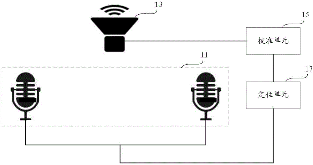
[0045] image 3 It is a schematic structural diagram of a sound source localization system in an embodiment of the present invention.

[0046] Such as image 3 As shown, in this embodiment, the sound source localization system provided by the present invention includes a linear microphone array ...


PUM


Abstract

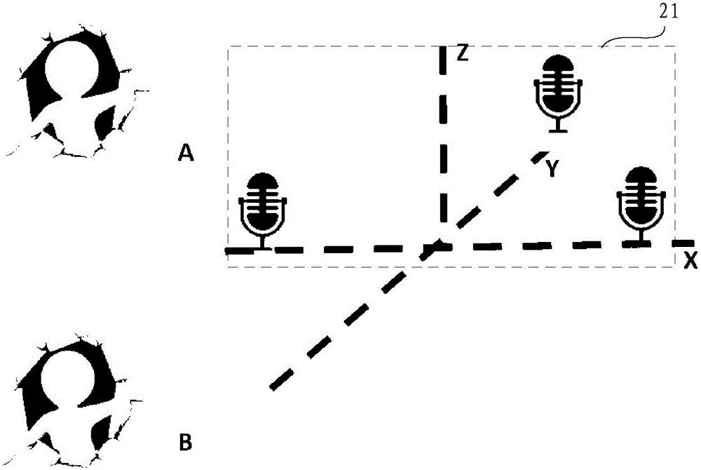
The present invention provides a sound source positioning system and method. The system comprises a dual-microphone array used for acquiring the sound information; a loudspeaker used for acquiring the sound source feedback information, wherein the loudspeaker and the dual-microphone array are not located in a same straight line; a calibration unit used for calibrating the frequency response, phase and amplitude of the sound source feedback information according to a preset parameter; a positioning unit used for positioning two suspected positions of a sound source in a predetermined plane according to the sound information, and determining the position of the sound source in the two suspected positions according to the calibrated sound source feedback information. According to the present invention, the loudspeaker usually comprised in the conventional equipment is utilized to acquire the sound source feedback information, and the positioned suspected position of the microphone array is determined according to the sound source feedback information generated by the sound sources of different distances, thereby realizing the plane positioning without needing to increase a microphone by combining the dual-microphone array with the loudspeaker, or realizing the stereo positioning by combining a three-microphone array with the loudspeaker.

Description

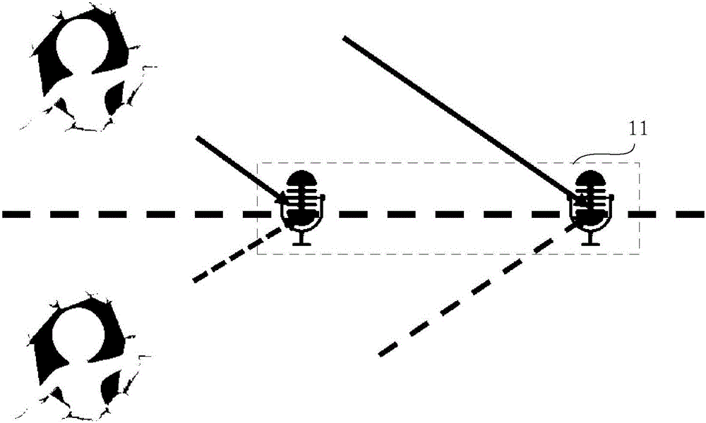
technical field [0001] The present application relates to the technical field of sound source localization, and in particular to a sound source localization system and method. Background technique [0002] Traditional sound positioning systems and methods are limited by microphone arrays. For example, linear microphone arrays can only achieve 180° positioning, but cannot achieve 360° positioning; planar microphone arrays can achieve 360° plane range positioning, but cannot realize three-dimensional space stereotaxic. [0003] figure 1 It is a schematic diagram of planar positioning of a linear microphone array in the prior art. Such as figure 1 As shown, when the linear microphone array 11 is positioned on a plane, two axisymmetric suspected positions are obtained, and the two suspected positions are symmetrical with respect to the line where the linear microphone array 11 is located. The positioning system based on the linear microphone array 11 cannot distinguish betwe...

Claims


Application Information

Patent Timeline
Patent Type & Authority Applications(China)
IPC IPC(8): G01S5/18
Inventor 徐荣强
Owner BEIJING HORIZON INFORMATION TECH CO LTD
Learn More