
Pulse signal cluster sorting method based on class merging

A pulse signal and category technology, which is applied in character and pattern recognition, instruments, computer parts, etc., can solve the problems of low correct rate of category numbers and discrepancies between the number of clusters and the number of real signals, etc.

Active Publication Date: 2016-10-26
HARBIN INST OF TECH
View PDF5 Cites 10 Cited by
  • Summary
  • Abstract
  • Description
  • Claims
  • Application Information

AI Technical Summary

Problems solved by technology

[0003] The purpose of the present invention is to solve the shortcomings of the low accuracy rate of the number of categories in the existing clustering results, and the number of clusters after the clustering and merging does not match the number of real signals, and propose a clustering and sorting of pulse signals based on category merging method

Method used


Image

  • Pulse signal cluster sorting method based on class merging
  • Pulse signal cluster sorting method based on class merging
  • Pulse signal cluster sorting method based on class merging

Examples


specific Embodiment approach 1

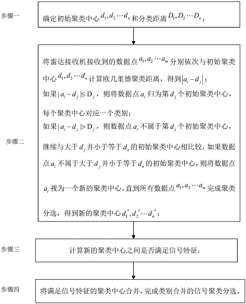
[0017] Specific implementation mode one: combine figure 1 To illustrate this embodiment, a method for clustering and sorting pulse signals based on category merging in this embodiment is specifically performed according to the following steps:

[0018] Step 1. Determine the initial clustering center d 1 , d 2 … d n and classification distance D 1 ,D 2 …D n , d 1 is the initial cluster center of the first category, d 2 is the initial cluster center of the second category, d n is the initial cluster center of the nth category, D 1 is the classification distance of the first category, D 2 is the classification distance of the second category, D n is the classification distance of the nth category, n is a positive integer;

[0019] Step 2, the data point a received by the radar receiver 1 ,a 2 …a m respectively with the initial cluster center d 1 , d 2 … d n Calculate the Euclidean clustering distance and get|a i -d j |, where, 1≤i≤m, 1≤j≤n,

[0020] if|a i -d...

specific Embodiment approach 2

[0025] Specific embodiment two: the difference between this embodiment and specific embodiment one is: in the step two Where k is the number of data points for each cluster center, a c For the data points contained in each cluster center, 1≤c≤k, k is a positive integer.

[0026] Other steps and parameters are the same as those in Embodiment 1.

specific Embodiment approach 3

[0027] Specific implementation mode three: the difference between this implementation mode and specific implementation mode one or two is: whether the signal characteristics are satisfied between the new cluster centers calculated in the step three; the specific process is called:

[0028] For the jitter signal, if the new cluster center satisfies the relationship:|d i '-d j '|≤(1+Δδ)D 0 , then d i ', d j 'Two cluster centers should be merged into the same category;

[0029] Among them, 1≤i≤n, 1≤j≤n, where d i ', d j 'respectively d 1 ',d 2 '...d n ′ in any two cluster centers, D 0 is the threshold parameter, and Δδ is the jitter value of 0.01-0.03; the threshold parameter is an artificial setting, an empirical value.

[0030] Other steps and parameters are the same as those in Embodiment 1 or Embodiment 2.


PUM


Abstract

The invention relates to a pulse signal cluster sorting method based on class merging. The method aims to overcome the defects that the class number accuracy in the existing cluster result is low and the cluster number is inconsistent with the real signal number after class merging. The pulse signal cluster sorting method based on class merging specifically comprises the following steps: 1, determining initial cluster centers and sorting distances; 2, obtaining new cluster centers; 3, calculating whether the new cluster centers satisfy signal features; and 4, merging the cluster centers satisfying the signal features, thereby accomplishing signal cluster sorting based on class merging. The method is applied in the field of signal processing.

Description

technical field [0001] The invention relates to a method for clustering and sorting pulse signals based on category merging. Background technique [0002] The classic signal clustering and sorting algorithm is based on the K-means clustering algorithm, and the traditional K-means algorithm uses a given cluster center to complete the signal sorting, so the selection of the cluster center largely determines the class of classification. The sum is correct or not. Therefore, the signal clustering algorithm generally adopts an improved clustering algorithm, that is, the first intercepted pulse signal parameters are selected as the clustering center, and according to Euclid's theorem, it is judged whether the subsequent pulse signal should become a new clustering center alone or whether it should into existing classes. However, the problem is that this clustering method cannot be clustered according to the different modulation types of pulse signals. The class center should cha...

Claims


Application Information

Patent Timeline
IPC IPC(8): G06K9/00G06K9/62
CPCG06F2218/12G06F18/23211
Inventor 赵彬季柄任李宏博宿愿
Owner HARBIN INST OF TECH
Learn More