
Hot body near-surface gradient temperature field real-time visual experiment device and experiment method

A technology of gradient temperature and experimental device, applied in the field of heat transfer experiments, can solve the problems of inability to realize real-time dynamic observation of gradient temperature field, difficulty in collecting temperature data, and lack of sight, and achieves simple structure, good demonstration effect, and intuitive demonstration. Effect

Inactive Publication Date: 2016-10-26
SHAANXI NORMAL UNIV
View PDF9 Cites 1 Cited by
  • Summary
  • Abstract
  • Description
  • Claims
  • Application Information

AI Technical Summary

Problems solved by technology

Real-time dynamic observation of the size and direction of the gradient temperature field cannot be realized; at the same time, the temperature gradient is often large near the surface of the hot body, that is, the temperature changes greatly within a very small distance, and limited by the size of the temperature sensing probe, the temperature Data collection is difficult or impossible
As one of the basic problems in the study of heat transfer, realizing the synchronous real-time dynamic display of the magnitude and direction of the gradient temperature field near the surface of a hot body is of great significance in the teaching of heat transfer, but no such experimental demonstration equipment has been seen so far.

Method used


Image

  • Hot body near-surface gradient temperature field real-time visual experiment device and experiment method
  • Hot body near-surface gradient temperature field real-time visual experiment device and experiment method
  • Hot body near-surface gradient temperature field real-time visual experiment device and experiment method

Examples


Embodiment 1

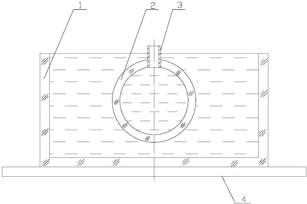
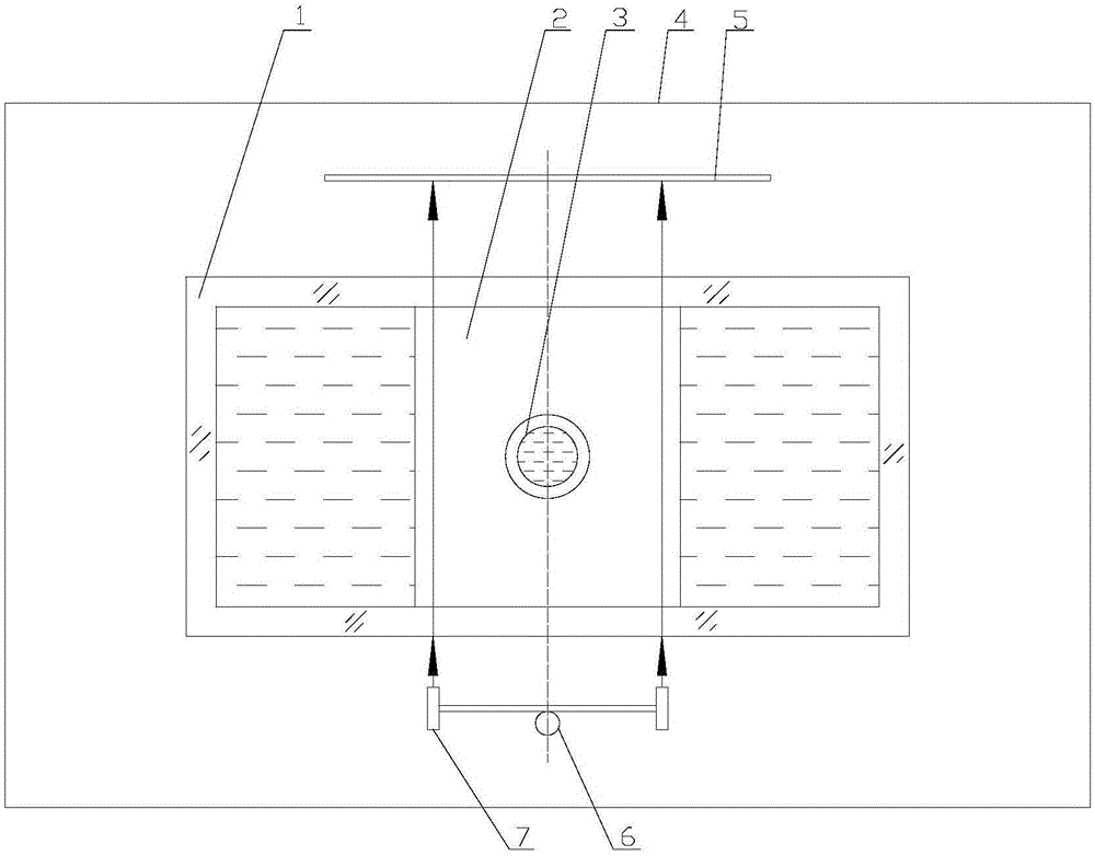
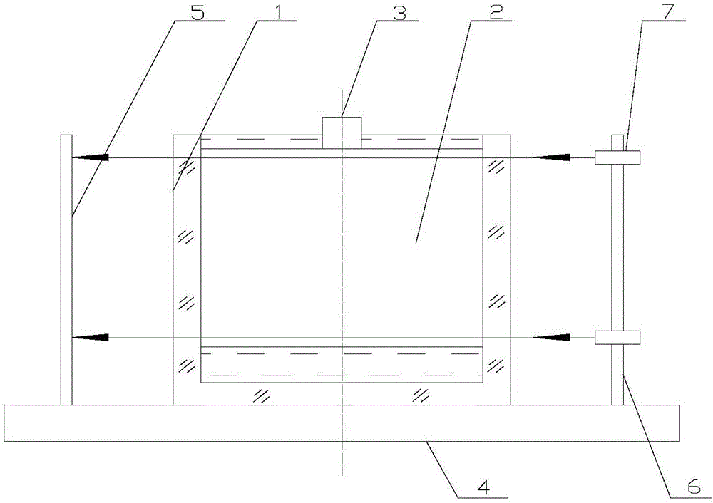
[0023] exist figure 1 , 2 In 3, the real-time visualization experimental device of the near-surface gradient temperature field of the thermal body in this embodiment is composed of a water tank 1, a water storage pipe 2, a water injection pipe 3, a base 4, a light screen 5, a laser bracket 6, and a semiconductor laser 7.

[0024] A water tank 1 is placed on the base 4, and the water tank 1 is a transparent rectangular parallelepiped water tank 1. The central position of the front side wall and the rear side wall in the water tank 1 is bonded with a water storage pipe 2 with optical glue, and the geometric shape of the water storage pipe 2 is a circle. Tubular shape, the central axis of the water storage pipe 2 is perpendicular to the front side wall and the rear side wall of the water tank 1, and the water storage pipe 2 is made of quartz glass or plexiglass. The top center of the water storage pipe 2 is glued with a water injection pipe 3, and the water injection pipe 3 comm...


PUM


Abstract

A hot body near-surface gradient temperature field real-time visual experiment device is characterized in that a transparent water tank is arranged on a base; a water storage pipe is arranged in the center positions of the front sidewall and the rear sidewall inside the water tank; a water injection pipe communicated with the water storage pipe is arranged on the top of the water storage pipe; a light screen is arranged on the base outside the rear side of the water tank, and a laser stand disposed on the central axis of the water storage pipe is arranged on the base outside the front side of the water tank; the laser stand is equipped with four semiconductor lasers which are disposed in the four vertex angle positions of a square symmetric around the central axis of the water storage pipe; and laser beams output by the four semiconductor lasers are transmitted through the front sidewall of the water tank, go along the outer wall of the water storage pipe, are transmitted through the rear sidewall of the water tank and are projected onto the light screen to form four light points in the four vertex angle positions of the square. The hot body near-surface gradient temperature field real-time visual experiment device has the advantages of simple structure, low cost, easy carrying, intuitive demonstration, good demonstration effect, and the like, and is applicable to demonstration experiment of heat transfer theory teaching.

Description

technical field [0001] The invention belongs to the technical field of heat transfer experiments, in particular to an experimental instrument or device for heat transfer in a gradient temperature field. Background technique [0002] Heat transfer is a science that studies the laws of heat transfer caused by temperature differences. Because there are temperature differences that promote heat transfer in nature and production technology, the theory of heat transfer is widely used in nature and various fields. The temperature difference is the driving force of heat transfer, and the size and direction of the temperature gradient determine the size and direction of the heat transfer speed. The research on the distribution of the gradient temperature field near the surface of a thermal body is mainly to determine the magnitude and direction of the gradient temperature field. The traditional method of dynamic display of the gradient temperature field distribution near the surface...

Claims


Application Information

Patent Timeline
Patent Type & Authority Applications(China)
IPC IPC(8): G09B23/16
CPCG09B23/16
Inventor 张宗权耿玉徐铭时俊仙田玉龙
Owner SHAANXI NORMAL UNIV
Learn More