Rotary output device and switch cabinet operating mechanism using the device

A technology of output device and power output shaft, which is applied to electric switches, electrical components, circuits, etc., can solve the problem of reverse misoperation of the output shaft, and achieve the effect of good limit effect, simple limit structure and convenient use.

Active Publication Date: 2019-01-11
XUJI GRP +2
View PDF5 Cites 0 Cited by
  • Summary
  • Abstract
  • Description
  • Claims
  • Application Information

AI Technical Summary

Problems solved by technology

[0003] The purpose of the present invention is to provide a rotary output device to solve the technical problem that the output shaft in the prior art only has one-way limit, which leads to the reverse misoperation of the output shaft; at the same time, the present invention also provides a rotary output device using the above Switchgear operating mechanism for output devices

Method used


Image

  • Rotary output device and switch cabinet operating mechanism using the device
  • Rotary output device and switch cabinet operating mechanism using the device
  • Rotary output device and switch cabinet operating mechanism using the device

Examples


Embodiment Construction

[0022] Embodiments of the present invention will be further described below in conjunction with the accompanying drawings.

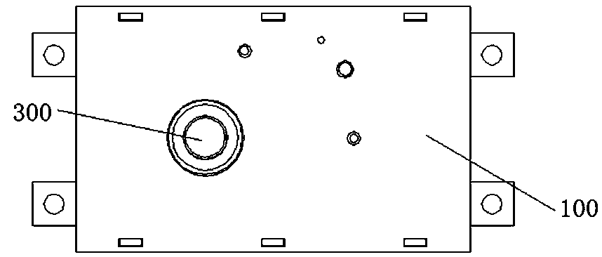
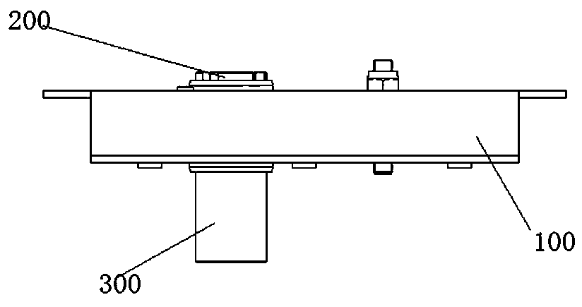
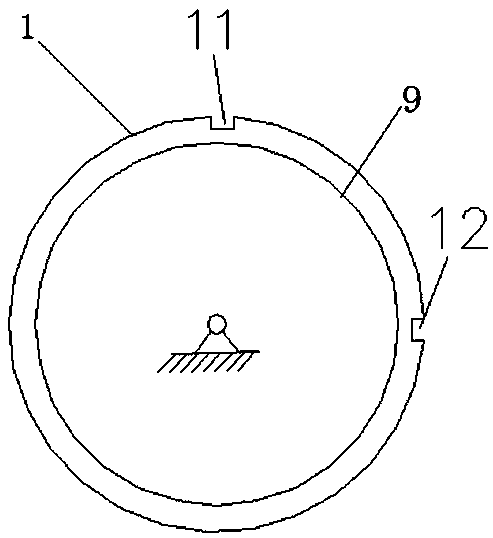
[0023] The specific embodiment of the switchgear operating mechanism provided by the present invention, such as Figure 1 to Figure 4 As shown, the switchgear operating mechanism in this embodiment includes a bracket 100, on which a power input shaft 300 and a power output shaft 200 are rotatably mounted, where the power input shaft 300 and the power output shaft 200 are coaxially arranged, and the power input The shaft 300 drives the power output shaft 200 to rotate through the driving transmission mechanism, and the power output shaft 200 rotates to realize the opening and closing operation. Here, the power input shaft and the power output shaft are respectively provided with corresponding cam discs, that is, the input cam 9 and the output cam 1 . The structure of the power input shaft, power output shaft and drive transmission mechanism here is the s...


PUM


Abstract

The invention relates to a rotary output device and a switch cabinet operating mechanism using the same. The rotary output device comprises a power output shaft, a power input shaft which drives the power output shaft to rotate through driving a transmission mechanism, and a bidirectional locking mechanism which locks the rotation of forward and backward directions of the power output shaft when the power output shaft rotates to a position, and the bidirectional locking mechanism has a locking state and an unlocking state. The invention provides the rotary output device, the power output shaft is driven by the power input shaft through driving the transmission mechanism, and when the power output shaft rotates to the position, the power output shaft is locked by using the bidirectional locking mechanism, the rotation of the power output shaft in the forward and backward directions is avoided, and thus the defect of a single direction limit is avoided.

Description

technical field [0001] The invention relates to a rotary output device and a switch cabinet operating mechanism using the device. Background technique [0002] In the field of switchgear operating mechanism, the input shaft drives the coaxially arranged output shaft to rotate through the transmission mechanism to realize the opening and closing station operation. For the isolating switch or the grounding switch, when the output shaft rotates to the closing position with the corresponding knife rod, the corresponding structure of the static end will carry out corresponding stop and limit on the output shaft through the knife rod, but this stop limit In fact, it is a one-way limit, which cannot directly limit the reverse rotation of the output shaft. At this time, the reverse operation of the output shaft can be directly operated without the input shaft. For example, when the energy storage device configured on the output shaft When the spring fails and accidentally drives th...

Claims


Application Information

Patent Timeline
Patent Type & Authority Patents(China)
IPC IPC(8): H01H9/24
CPCH01H9/24
Inventor 吴小钊刘永庆李鹏张文凯李长鹏郑晓果赵洪柏白维正
Owner XUJI GRP
Why Eureka
Try Eureka