Reversely insert usb socket

A positive and negative insertion, metal technology, applied in coupling devices, contact parts, electrical components, etc., can solve the problems of difficult and large current passing, short circuit of metal middle plate, etc., to reduce impedance and reduce temperature rise effect.

Active Publication Date: 2020-02-14
SHENZHEN EVERWIN PRECISION TECH
View PDF7 Cites 0 Cited by
  • Summary
  • Abstract
  • Description
  • Claims
  • Application Information

AI Technical Summary

Problems solved by technology

[0003] The upper and lower two groups of conductive terminals respectively include a pair of ground terminals located on the outermost side and a pair of power terminals located in the middle. At present, in the case of realizing fast charging, the ground terminals and power terminals are required to allow a large current to pass through, but adding Thickening the power terminals will easily lead to a short circuit with the metal middle plate, while widening the power terminals is limited by the small spacing between terminals, making it difficult to effectively realize the passage of large currents

Method used


Image

  • Reversely insert usb socket
  • Reversely insert usb socket
  • Reversely insert usb socket

Examples


Embodiment 1

[0030] The following will combine Figure 1-Figure 10 The technical solution and technical principle of Embodiment 1 of the present application are introduced in detail.

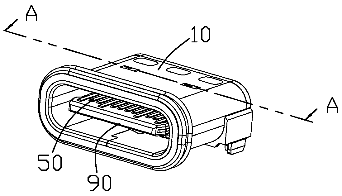
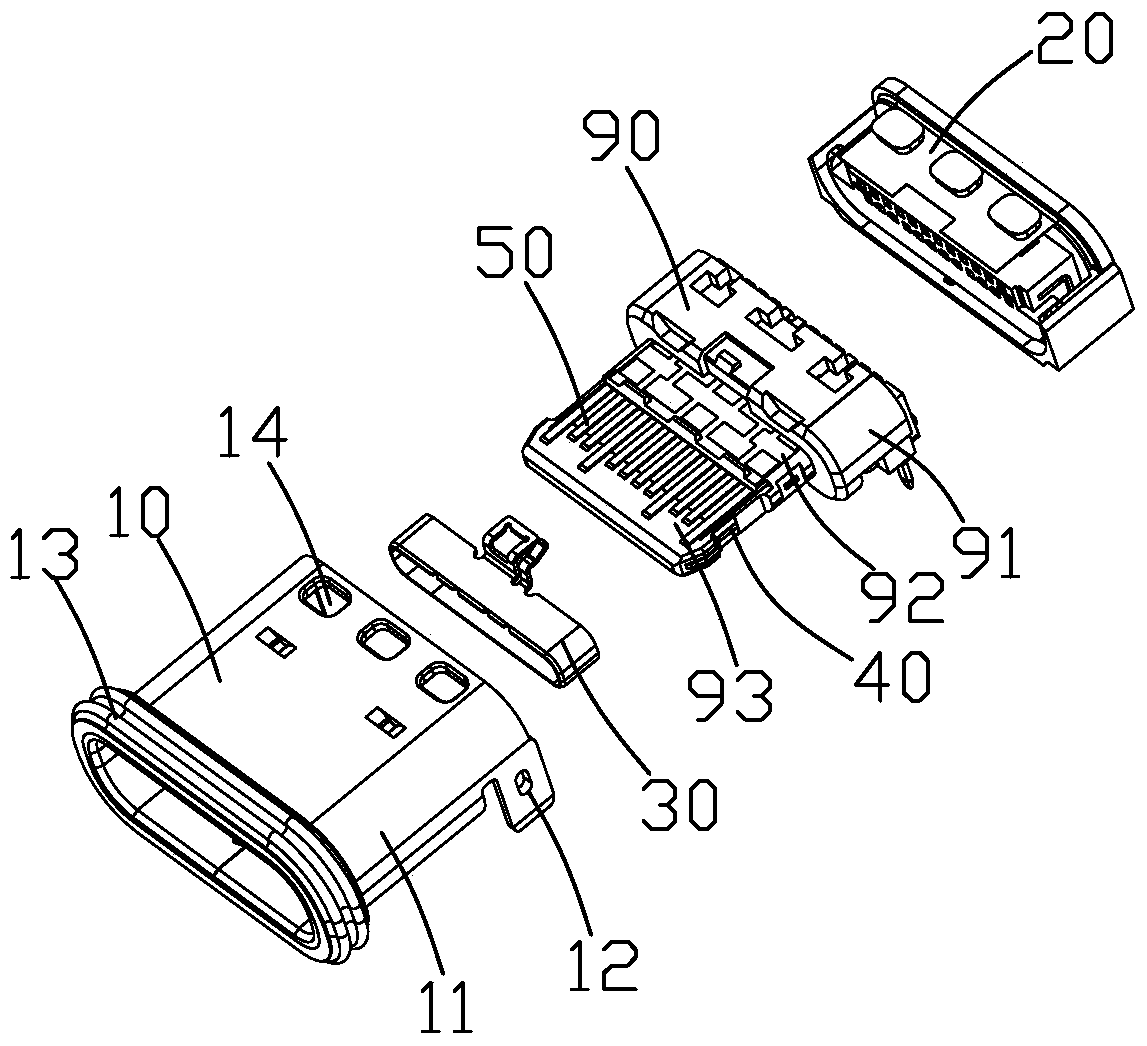
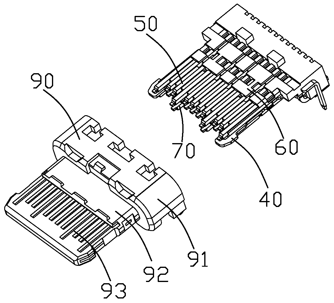
[0031] see Figure 1 to Figure 4 As shown, the USB socket of the present application includes a metal middle plate 40, a first terminal group 50 located on the upper and lower sides of the metal middle plate 40, a second terminal group 70, connecting the first terminal group 50 and the The metal middle plate 40 is integrally formed with the first insulator 60, the second insulator 80 is formed on the second terminal group 70, and the third insulator 60 and the second insulator 80 are integrally formed. The insulator 90, the grounding member 30 sleeved on the third insulator 90, the metal shell 10 surrounding the third insulator 90, and the rear end of the metal shell 10 are integrally formed to eliminate the metal shell 10 and the fourth insulator 20 in the gap between the third insulator 90 .

[0032] Th...

Embodiment 2

[0046] see Figure 11 , Figure 12 Compared with the first embodiment, the second embodiment of the present application shown is different from the second embodiment in that: according to the standard specification of the USB-IF association, the first and second ground terminals 50a, 70a are connected to the first and second ground terminals. The lengths of the front ends of the two power supply terminals 50b and 70b are greater than the lengths of the front ends of the first and second signal terminals 50c and 70c, and the difference in length is 0.5mm. As a result, in the first embodiment, the metal middle plate 40 must be completely cut. form two separate parts.

[0047] In the second embodiment, the front end extension lengths of the first and second ground terminals 50a, 70a and the first and second power supply terminals 50b, 70b are reduced to only be longer than the first and second signal terminals 50c, 70c 0.2mm state, and then the front end of the metal middle pla...


PUM


Abstract

The invention discloses a pro and con-pluggable USB socket, which comprises a metal middle board, a first terminal group and a second terminal group symmetrically located at two vertical sides of the metal middle board respectively, and an insulated body for enabling the first terminal group and the second terminal group and the metal middle board to be formed as a whole, wherein the first terminal group and the second terminal group comprise two first grounding terminals and two second grounding terminals located at the outermost side, a plurality of first signal terminals and two first power terminals located between the two first grounding terminals and a plurality of second signal terminals and two second power terminals located between the two second grounding terminals; the metal middle board between the first signal terminals and the first power terminals of the first terminal group and the second signal terminals and the second power terminals of the second terminal group is removed; and the metal middle board is only located between the first grounding terminals and the second grounding terminals. The pro and con-pluggable USB socket can effectively support high-current charging.

Description

technical field [0001] This application relates to an input and output type electrical connector, especially a USB socket with front and back insertion. Background technique [0002] The USB3.1 Type C interface is a new interface standard launched by the USB-IF Association in 2014. This standard takes into account both size and performance, and is suitable for applications on smart terminals, but it is not backward compatible. It generally includes a metal middle plate, two sets of conductive terminals arranged on the upper and lower sides of the metal middle plate, and an insulating material that holds the metal middle plate and the conductive terminals as a whole. The metal middle plate is used to shield the high-frequency interference of the upper and lower two sets of conductive terminals, limited by the size, the distance between the two sets of conductive terminals and the metal middle plate is very small, and the terminal thickness is 0.12mm Next, the distance betwee...

Claims


Application Information

Patent Timeline
Patent Type & Authority Patents(China)
IPC IPC(8): H01R13/6585H01R13/02H01R13/648
CPCH01R13/02H01R13/648H01R13/6585
Inventor 张秀华
Owner SHENZHEN EVERWIN PRECISION TECH
Why Eureka
Try Eureka