Supercharge Your Innovation With Domain-Expert AI Agents!

Suction channel for an extractor device for conveying cut waste strips of a film web

A technology of suction equipment and channels, which is used in the transportation of bulk materials, conveyors, applications, etc., can solve the problems of the application of edge strips with no clear composition, the inability to provide, and the impossibility of considering material differences, etc. Effect

Inactive Publication Date: 2016-10-26
WINDMOELLER & HOELSCHER GMBH
View PDF7 Cites 0 Cited by
  • Summary
  • Abstract
  • Description
  • Claims
  • Application Information

AI Technical Summary

Problems solved by technology

[0003] However, the known solution has the disadvantage that it is not possible to apply trim strips of defined composition to several extrusion devices
To this end, a corresponding separation must be ensured, which cannot be provided by known suction channels
It is also currently not possible to take into account possible material differences between the trim strips at the edges and the trim strips in the middle and separate them for individual recycling levels

Method used


Image

  • Suction channel for an extractor device for conveying cut waste strips of a film web
  • Suction channel for an extractor device for conveying cut waste strips of a film web
  • Suction channel for an extractor device for conveying cut waste strips of a film web

Examples


Embodiment Construction

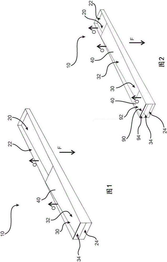
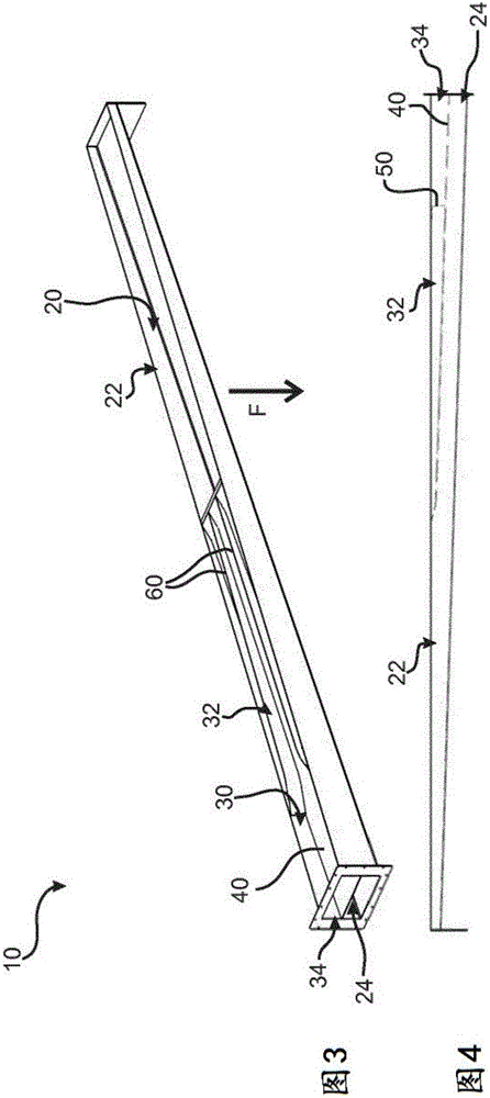
[0038] exist figure 1 An embodiment of the suction channel 10 according to the invention is schematically shown in . It can be clearly seen here that the common partition wall 40 separates the two individual channel sections 20 and 30 from one another over the entire width of the suction channel 10 . Each of the two channel sections 20 and 30 has its own channel section inlet 22 and 32 . One or more trim strips 210 of the film web 200 can be sucked in through the completely open channel section inlets 22 and 32 , which here are formed with an upward opening direction O. FIG. The two channel inlets 22 and 32 are spaced apart from one another transversely to the conveying direction F of the film web 200 shown, so that differently positioned and cut trim strips 210 are sucked in depending on their position and are drawn individually in the corresponding channel section 20 and 30 are booted. At the lower left end, the two channel sections 20 and 30 lead to the corresponding cha...


PUM


Abstract

The invention relates to a suction channel (10) for an extractor device (100) for conveying cut waste strips (210) of a film web (200) transversely with respect to the conveying direction (F) of the film web (200), having a first channel portion (20) and a second channel portion (30) separated from the first channel portion (20) by at least one common partition (40), wherein the first channel portion (20) and the second channel portion (30) have at least one channel portion output (24, 34) in each case and at least one channel portion input (22, 32) in each case, and wherein the channel portion inputs (22, 32) of the two channel portions (20, 30) are disposed spaced apart from one another transversely with respect to the conveying direction (F) of the film web (200).

Description

technical field [0001] The invention relates to a suction channel for a suction device for conveying cut, in particular continuous, trim strips of a film web, and to a suction device with a corresponding suction channel. Background technique [0002] It is basically known to cut edge strips and / or middle strips during the production of the film web. This is used to ensure the exact dimensions of the film to be manufactured. Trim strips, also called edge strips or middle strips, must be separated in the machine. For separation, it is known to provide a suction device with a suction channel. Such a solution is shown, for example, in DE 10 2012 108 196 A1. In this document it is described how the individual trim strips in the form of edge strips and / or middle strips are guided by means of a suction device in a common suction channel. The common suction channel extends transversely to the conveying direction of the film web and accordingly guides the suctioned trim strands s...

Claims


Application Information

Patent Timeline
IPC IPC(8): B65G53/24B65G53/52B29C48/07B29C48/10
CPCB65G53/24B65G53/52B29B17/0005B29L2007/008Y02W30/62B29C48/07B29C48/10B29C48/274B29C48/277Y02P70/10B02C18/148B29K2105/26
Inventor F·宗德曼F·霍夫曼T·塞雷尔
Owner WINDMOELLER & HOELSCHER GMBH
Features
  • R&D
  • Intellectual Property
  • Life Sciences
  • Materials
  • Tech Scout
  • Unparalleled Data Quality
  • Higher Quality Content
  • 60% Fewer Hallucinations
Learn More