
Method for detecting faults in fuel delivery of an internal combustion engine

A technology of fuel delivery and internal combustion engine, which is applied to fuel injection device, engine testing, fuel injection control, etc., can solve problems such as fuel-air-mixture influence, and achieve the effect of simple and rapid identification

Active Publication Date: 2021-03-05
ROBERT BOSCH GMBH
View PDF6 Cites 0 Cited by
  • Summary
  • Abstract
  • Description
  • Claims
  • Application Information

AI Technical Summary

Problems solved by technology

However, faulty components of inactive paths can also lead to an influence on the fuel-air mixture due to, for example, undesired supply of fuel into the combustion chamber

Method used


Image

  • Method for detecting faults in fuel delivery of an internal combustion engine
  • Method for detecting faults in fuel delivery of an internal combustion engine
  • Method for detecting faults in fuel delivery of an internal combustion engine

Examples


Embodiment Construction

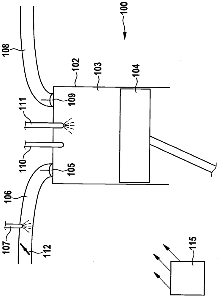
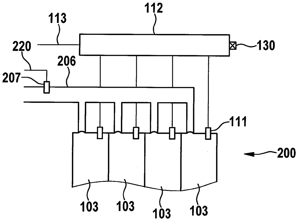
[0025] exist Figure 1a An internal combustion engine 100 is shown schematically and in simplified form in which the method according to the invention can be carried out. Internal combustion engine 100 has, for example, four combustion chambers 103 and an intake duct 106 , which is connected, for example, to each of combustion chambers 103 .

[0026] The intake manifold 106 here has, for each combustion chamber 103 , a first fuel injector 107 which is arranged in sections of the intake manifold shortly before the combustion chambers. The fuel injector 107 is thus used for intake manifold injection. All fuel injectors 107 are connected to the low pressure line via inlet lines 120 . Furthermore, each combustion chamber 103 has a fuel injector 111 for direct injection.

[0027] Also shown is a high-pressure accumulator 112 , the so-called rail, to which fuel injectors 111 for direct injection are connected. The high-pressure accumulator 112 is connected via an inlet line 113 t...


PUM


Abstract

The invention relates to a method for detecting faults in the fuel delivery of an internal combustion engine (100) in which intake manifold injection and direct injection are provided, wherein a high-pressure system is provided for the direct injection, the high-pressure system including a high-pressure accumulator fuel injector (112) and fuel injector (111) for each combustion chamber (103) of the internal combustion engine (100, 200) for metering fuel from the high-pressure accumulator (112), wherein, when direct injection is not When a deviation of the fuel-air-ratio from a predetermined value in at least one of the combustion chambers (103) is detected, the pressure in the high-pressure accumulator (112) is checked, and wherein, when a high-pressure In the event of an undesired pressure drop in the pressure accumulator (112), a fault in the high pressure system during combustion delivery is inferred.

Description

technical field [0001] The invention relates to a method for detecting faults in the fuel delivery of an internal combustion engine in which intake manifold injection and direct injection are provided. Background technique [0002] A possible method for fuel injection in Otto engines is port injection, which is increasingly being replaced by direct fuel injection. The latter method leads to a significantly better fuel distribution in the combustion chamber and thus to a better power yield with lower fuel consumption. [0003] Furthermore, gasoline motors with a combination of intake manifold injection and direct injection, the so-called dual system, are also preferred. This is advantageous precisely under increasingly stringent emission requirements or emission limit values, since the intake manifold injection results in better emission values ​​than direct injection, for example in the medium load range. [0004] Depending on the system configuration, for example operatin...

Claims


Application Information

Patent Timeline
Patent Type & Authority Patents(China)
IPC IPC(8): F02M65/00F02D41/22F02M55/02
CPCF02D41/22F02M65/003F02D2041/224F02M55/025F02D41/1456F02D41/221F02D41/3094F02D2041/3881F02D2041/389F02D2200/0602
Inventor D.S.阿耶姆勒O.阿本德罗特J-C.阿诺尔德A.布劳
Owner ROBERT BOSCH GMBH
Learn More