

Scanning Measuring Device With Thermally Neutral Axis
A technology of measuring device and axis of rotation, applied in the direction of measuring device, active optical measuring device, bearing/suspension of movable parts of measuring device, etc., can solve the problems of multi-part and overall space, large power demand, inaccurate measurement results, etc. , to achieve the effect of high rigidity and large load bearing capacity
- Summary
- Abstract
- Description
- Claims
- Application Information
AI Technical Summary
Problems solved by technology
Method used
Image

Examples
Embodiment Construction
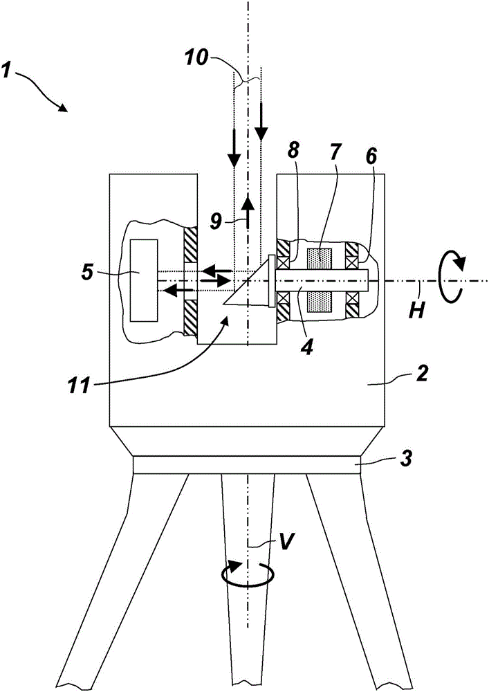
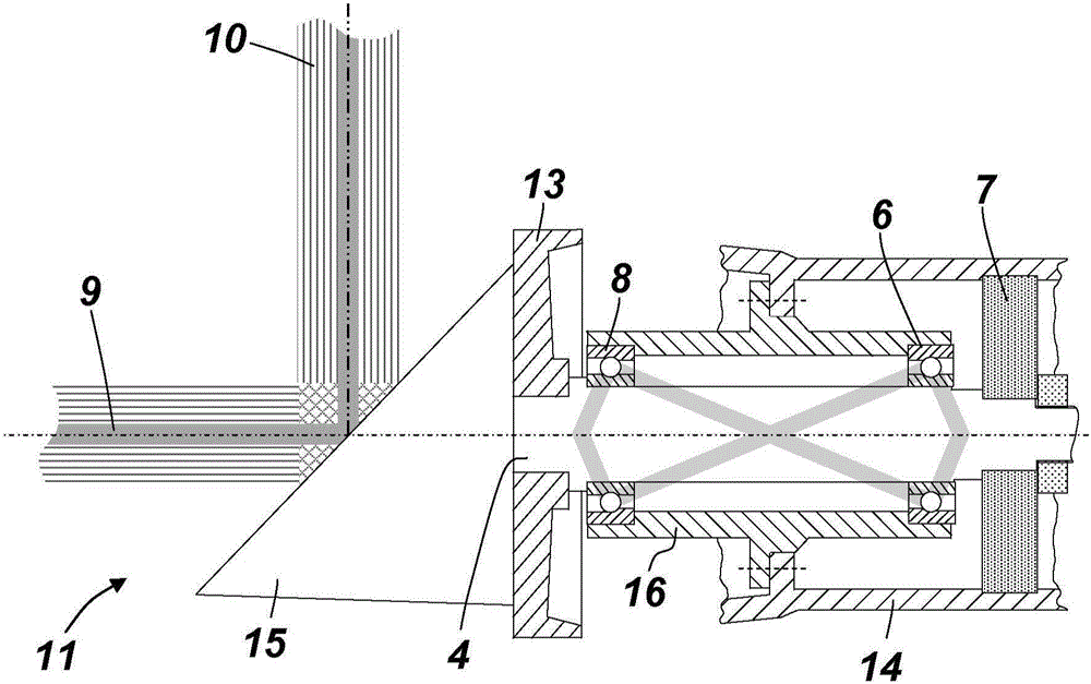
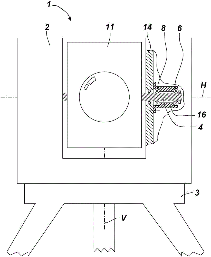
[0033] figure 1 An embodiment of a measuring device 1 according to the invention is shown, namely a laser scanner with a rapidly rotating horizontal axis H for emitting a laser beam and a slow the vertical axis V. The measuring device 1 also has a housing 2 mounted on the base 3 such that the housing 2 can be rotated about the base axis V; and a beam deflection unit 11 mounted on the housing by means of an axis 4 In the body 2, the beam deflection unit 11 can be rotated about the axis of rotation H. Positioned in the housing 2 is a beam transmitting and beam receiving unit, which in the example shown is combined into one unit 5 . In this case, the transmission beam 9 is emitted onto the beam deflection unit 11 and sent via the beam deflection unit 11 out into the environment. The reflected receive beam 10 is deflected in the same way back onto the beam receiving unit 5 . In order for the transmission beam 9 to exit the housing 2 onto the beam deflection unit 11 , an optica...
PUM
 Abstract
Description
Claims
Application Information