
Threshing chamber concave plate of harvester

A threshing room and harvester technology, which is applied in threshing equipment, applications, agricultural machinery and implements, etc., can solve the problems of crop weed discharge, heavy screen surface load, and large thickness of partitions, so as to reduce cleaning load and damage. Small, damage-reducing effect

Inactive Publication Date: 2016-11-09
HENAN RICHUANG GENERAL MACHINERY MFR
View PDF5 Cites 0 Cited by
  • Summary
  • Abstract
  • Description
  • Claims
  • Application Information

AI Technical Summary

Problems solved by technology

[0003] like figure 1 When the existing harvester threshing chamber uses the grid concave plate 10, because the grid concave plate 10 is composed of steel wires and partitions, under the limitation of material strength and structure, the steel wires are too thin and easy to break, and the distance between the steel wires is too small. Plate punching cannot be realized, so the gap between the various parts of the grid concave plate 10 cannot be made very small, and the effect of sufficient grain leakage and filtering straw cannot be achieved. If it is too large, it will cause more straw to enter the cleaning system. At the same time, due to the strength requirement, the thickness of the partition is too large, so the spacing cannot be too close, and the number of combing and uniformity of the grains is insufficient, which will cause small grains. Crops are discharged with weeds
see figure 2 , although the use of the punching concave plate 20 can control the size of the holes and the density of the hole arrangement, the surface of the punching concave plate 20 is smooth, and there is a problem that the strength of combing the grains is not enough, which will cause small crops with small grains weed discharge
[0004] The grid concave plate 10 and the punching concave plate 20 can only work on crops with large grain particles. When encountering crops with small grain particles, the combing ability and the ability to filter straws are insufficient, which will cause the crop grains with small grain particles to be damaged. The stalks will be discharged together with the stalks, and the stalks will easily enter the cleaning room, causing the serious consequences of overloading the sieve surface, inability to clean completely, dirty grains in the granary, and spreading grain at the end of the sieve surface, which has caused great harm to farmers. The economic loss is not conducive to the advancement of mechanized harvesting of crops with small grains

Method used


Image

  • Threshing chamber concave plate of harvester
  • Threshing chamber concave plate of harvester
  • Threshing chamber concave plate of harvester

Examples


Embodiment Construction

[0027] Exemplary embodiments of the present invention will be described in detail below with reference to the accompanying drawings. The description of the exemplary embodiments is for the purpose of illustration only, and in no way limits the invention and its application or usage.

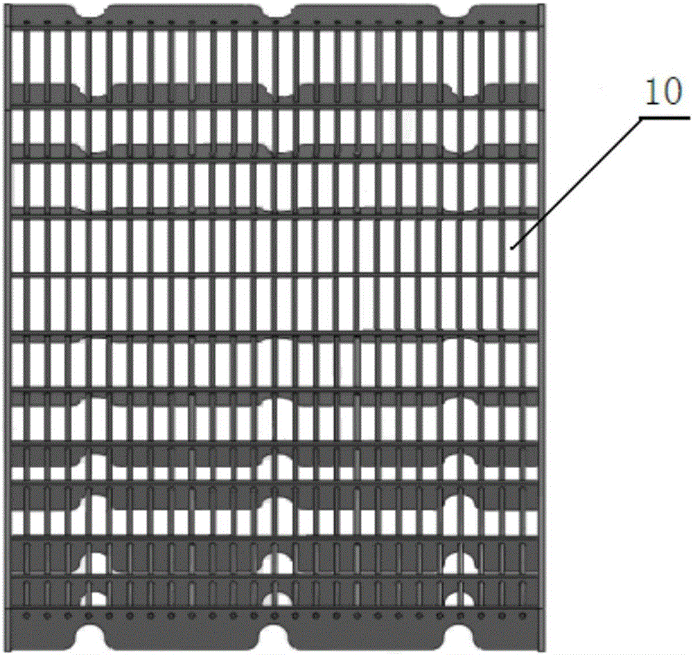
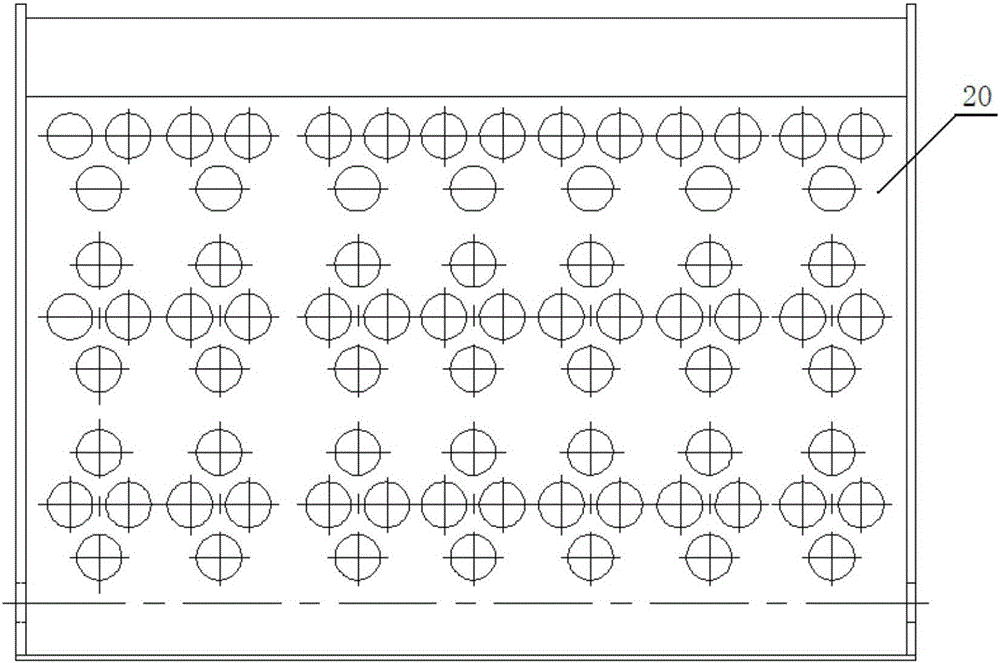
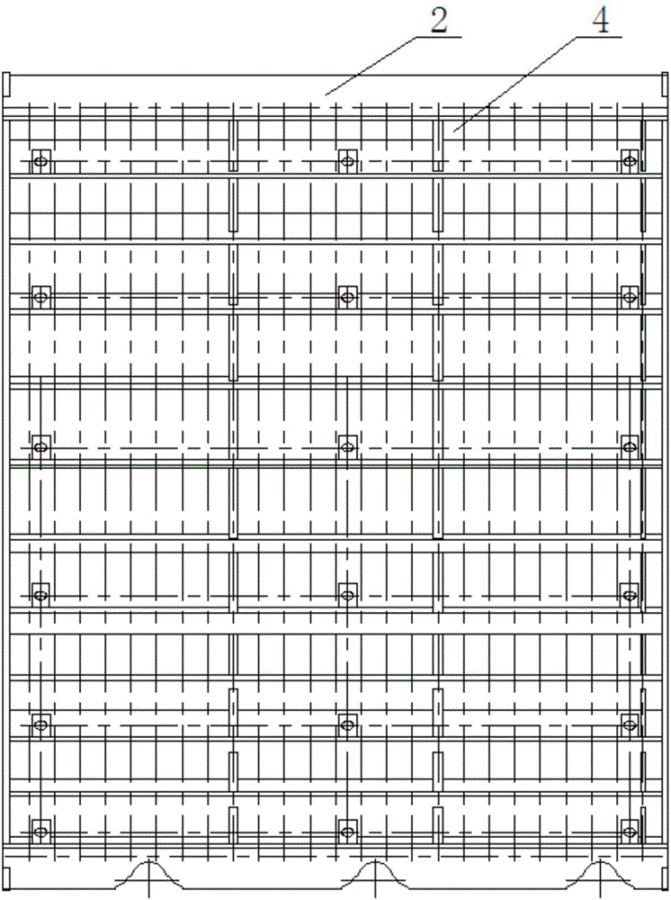
[0028] see image 3 , according to the present invention for the threshing chamber concave plate harvester, including: a support frame 2 and a mesh concave screen 4. The support frame 2 is fixedly arranged under the drum of the threshing chamber (not shown in the figure), and is used to fix the mesh concave plate sieve 4; the mesh concave plate sieve 4 is arranged on the support frame 2, and is used for filtering the grains after detaching and straw. The threshed grains are filtered through the mesh concave plate sieve and then fall into the cleaning chamber.

[0029] Mesh concave screen 4 is formed by lapping horizontal steel wire 5 and longitudinal steel wire 6, Figure 5 shows a front view...


PUM


Abstract

The invention discloses a threshing chamber concave plate of a harvester. The threshing chamber concave plate comprises a support frame and a reticular concave grate, wherein the support frame is fixedly arranged below a threshing chamber roller, and the reticular concave grate is arranged on the support frame and is formed by lap joint of horizontal steel wires and longitudinal steel wires; threshed seeds fall into a cleaning chamber after filtered by the reticular concave grate. The reticular concave grate can fully comb grain seeds, the grain seeds can be prevented from being discharged from a straw outlet and entering the cleaning chamber, and the purposes that the seeds are cleaner and the running amount is small are realized, and damage to the seeds and straw can be reduced. Besides, the damage degree of the threshing chamber concave plate of the harvester to the straw is small, the straw can be discharged from the straw outlet favorably, and the cleaning load is further reduced.

Description

technical field [0001] The invention relates to the technical field of crop harvesting equipment, in particular to a concave plate for a threshing chamber of a harvester. Background technique [0002] The technical background related to the present invention will be described below, but these descriptions do not necessarily constitute the prior art of the present invention. [0003] Such as figure 1 When the existing harvester threshing chamber uses the grid concave plate 10, because the grid concave plate 10 is composed of steel wires and partitions, under the limitation of material strength and structure, the steel wires are too thin and easy to break, and the distance between the steel wires is too small. Plate punching cannot be realized, so the gap between the various parts of the grid concave plate 10 cannot be made very small, and the effect of sufficient grain leakage and filtering straw cannot be achieved. If it is too large, it will cause more straw to enter the ...

Claims


Application Information

Patent Timeline
IPC IPC(8): A01F12/24
CPCA01F12/24
Inventor 徐锋魏本同赵玉成朱应信
Owner HENAN RICHUANG GENERAL MACHINERY MFR
Learn More