
Knotter and knotting system with the knotter

A knotter and sleeve technology, applied in the field of knotter system and knotter, can solve the problems of high sharpness requirements of the cutting knife, delaying the operation, etc. Effect

Active Publication Date: 2018-08-28
BEIJING MED ZENITH MEDICAL SCI CORP LTD
View PDF6 Cites 1 Cited by
  • Summary
  • Abstract
  • Description
  • Claims
  • Application Information

AI Technical Summary

Problems solved by technology

[0008] The purpose of the present invention is to provide a knotter and a minimally invasive knotting system with the knotter, which solves the problem that the sharpness of the cutting knife is too high in the knotter in the prior art, and once the cutting blade is damaged Problems That Can Delay Surgery

Method used


Image

  • Knotter and knotting system with the knotter
  • Knotter and knotting system with the knotter
  • Knotter and knotting system with the knotter

Examples


Embodiment Construction

[0028] Embodiments of the present invention will be further described in detail below in conjunction with the accompanying drawings and examples. The following examples are used to illustrate the present invention, but should not be used to limit the scope of the present invention.

[0029] In the description of the present invention, it should be noted that the terms "center", "longitudinal", "transverse", "upper", "lower", "front", "rear", "left", "right", " The orientations or positional relationships indicated by "vertical", "horizontal", "top", "bottom", "inner" and "outer" are based on the orientations or positional relationships shown in the drawings, and are only for the convenience of describing the present invention and Simplified descriptions, rather than indicating or implying that the device or element referred to must have a particular orientation, be constructed and operate in a particular orientation, and thus should not be construed as limiting the invention. ...


PUM


Abstract

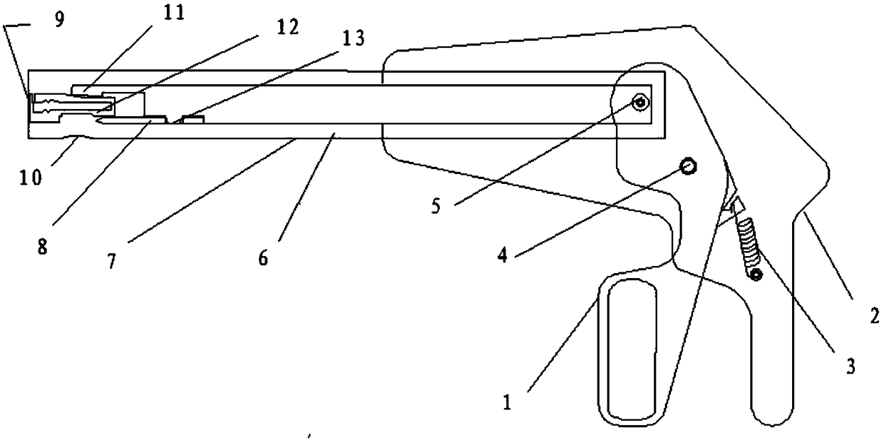
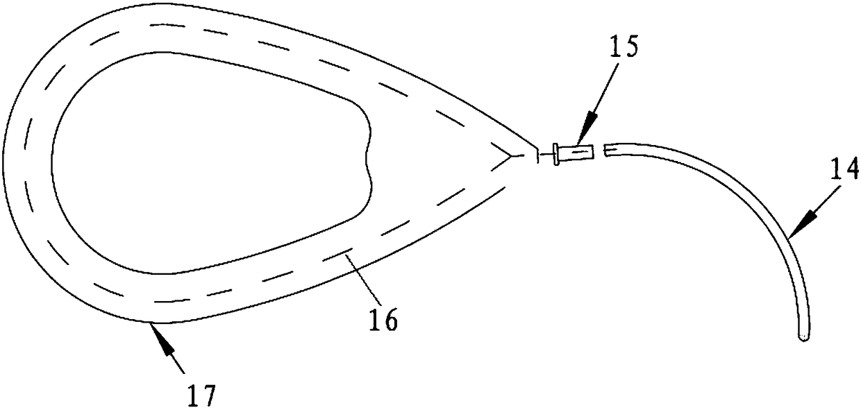
The invention relates to the technical field of surgical instruments, and provides a knotter and a knotting system with the knotter. Wherein, the knotter includes a shearing knife arranged at the front end of the transmission rod, the handle of the shearing knife is stretched by an elastic member, and the handle is closed and cuts the suture under the extrusion of the transmission rod. The knotter of this scheme adopts the shearing knife to replace the cutting knife of the prior art, and drives the shearing knife to close through the transmission rod to realize the shearing function. Obviously, when the suture is cut with scissors, the sharpness of the blade is greatly reduced, which can be achieved by ordinary processing methods, thereby greatly reducing the cost while ensuring reliability; The wear is reduced, which greatly prolongs the service life of the product, and can realize the thread cutting function after knotting faster and better.

Description

technical field [0001] The invention relates to the technical field of surgical instruments, in particular to a knotter and a knotting system with the knotter. Background technique [0002] Traditionally, there are various disadvantages when the knotting of deep parts is completed by manual winding. For example, it is time-consuming and labor-intensive, and it is necessary to manually cut the suture with scissors after repeated several times, and the knotting effect and success rate depend too much on the proficiency of the operator. [0003] In order to solve the above problems, the patent No. CN202892020U discloses a minimally invasive knotting system, which can be sutured and knotted in a minimally invasive environment, and is mainly suitable for minimally invasive replacement of heart valves and all intrathoracic soft tissue repairs. Deep stitching. The minimally invasive knotting system is easy to operate, and the operation of cutting the suture can be completed at th...

Claims


Application Information

Patent Timeline
Patent Type & Authority Patents(China)
IPC IPC(8): A61B17/04
CPCA61B17/0469A61B17/0467A61B2017/0488A61B2017/0454A61B2017/0474
Inventor 孟坚谢保歧马志伟张志武窦圣博周晓军吴康可大年
Owner BEIJING MED ZENITH MEDICAL SCI CORP LTD
Learn More