A bladder glue brushing device

A technology of brushing glue and bladders, which is applied to the device and coating of the surface coating liquid, which can solve the problems of low efficiency and inconvenience, and achieve the effect of preventing glue from sticking to hands, strong practicability and high precision

Active Publication Date: 2018-06-05
漳州华飞体育用品有限公司
View PDF6 Cites 0 Cited by
  • Summary
  • Abstract
  • Description
  • Claims
  • Application Information

AI Technical Summary

Problems solved by technology

Thus, it can be seen that the traditional glue brushing method is not only inconvenient, but also inefficient. Therefore, it is necessary to develop a bladder glue brushing device to improve the bladder glue brush efficiency

Method used


Image

  • A bladder glue brushing device
  • A bladder glue brushing device
  • A bladder glue brushing device

Examples


Embodiment 1

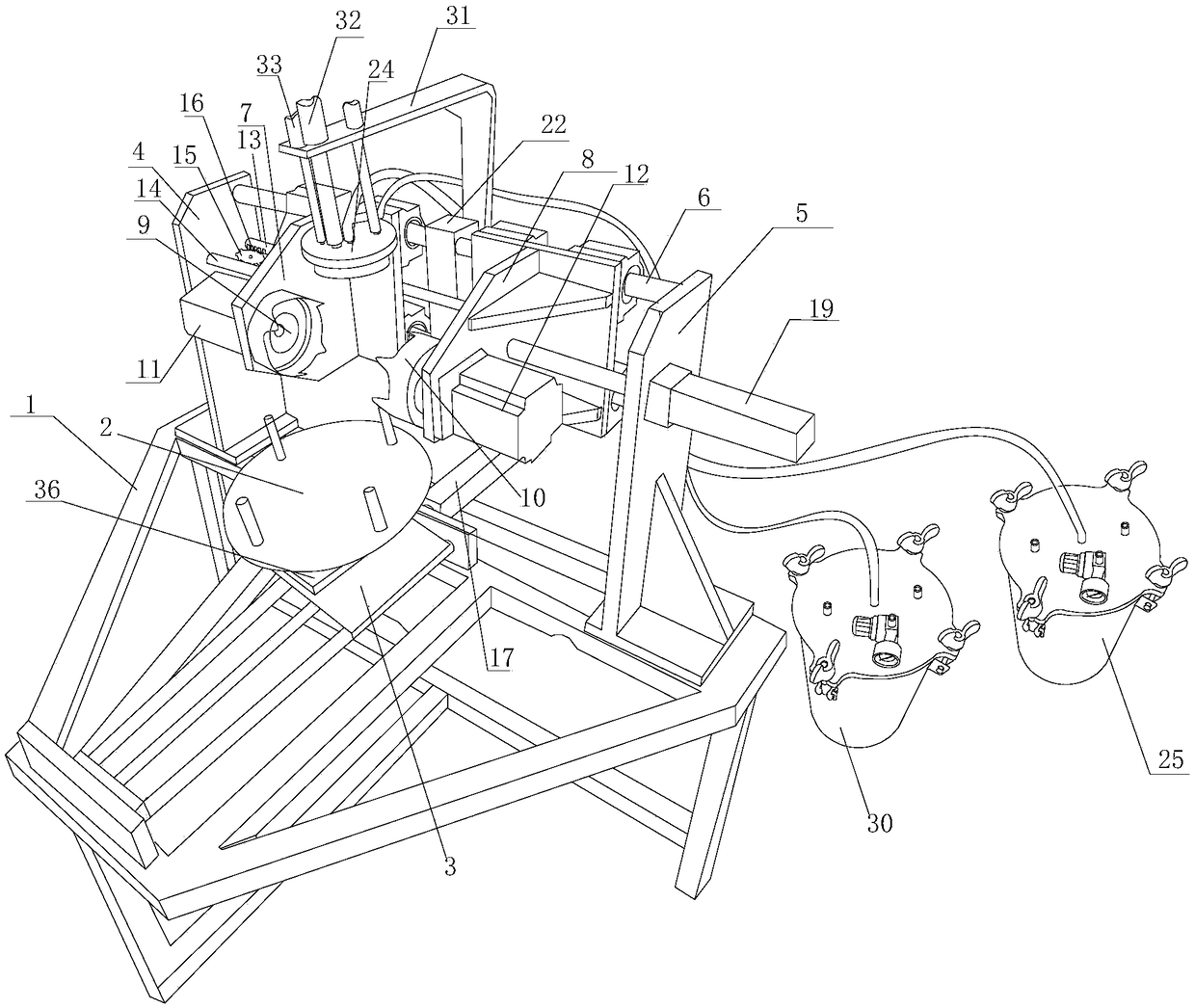
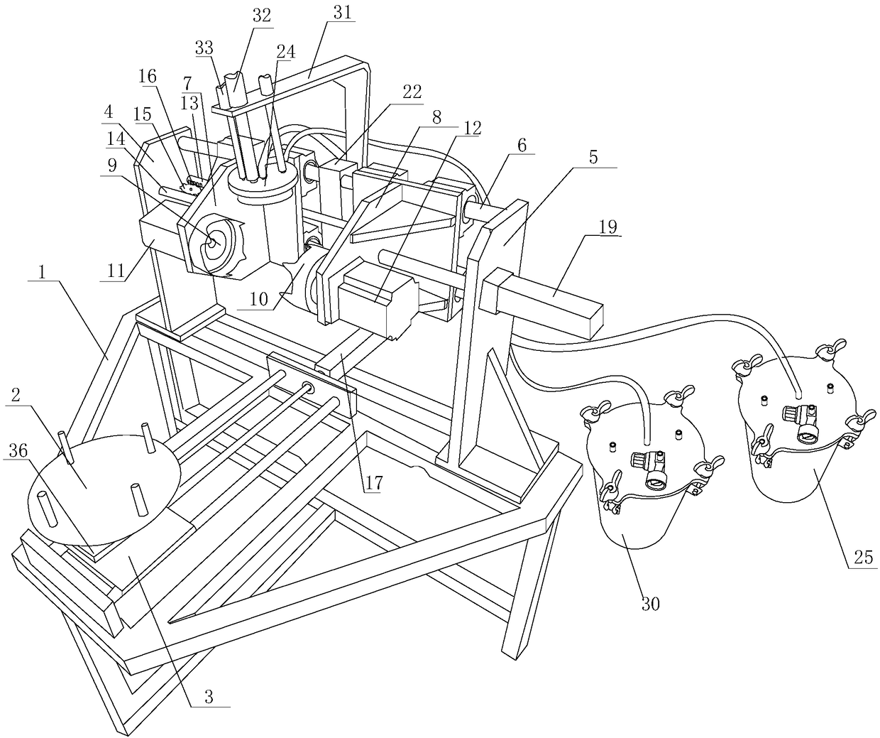
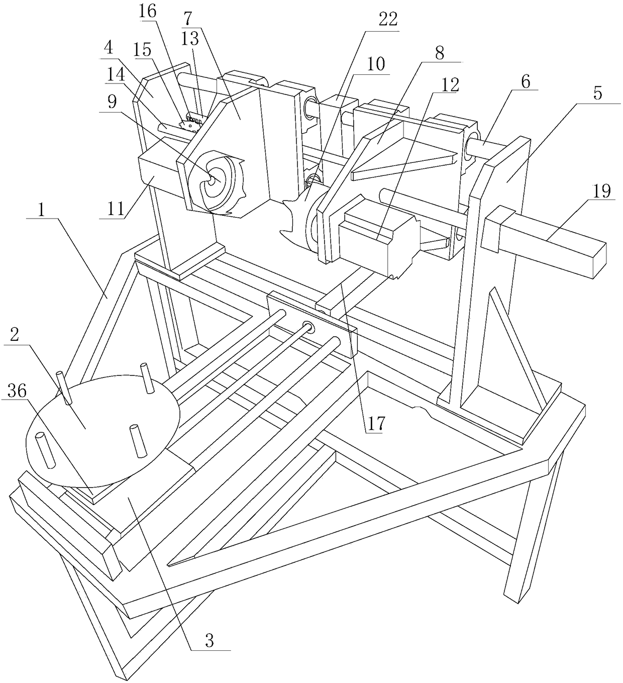
[0020] Such as Figure 1-7 Shown: a bladder brushing device, which includes a transmission system and a glue brushing machine; the transmission system includes a frame 1, which is arranged on the frame 1 and is used to clamp the bladder and drive the bladder to rotate The jig and the supporting assembly located directly below the jig, the supporting assembly includes a tray 2 and a rotating lifting device arranged under the tray 2 and connected to the tray 2, the rotating lifting device makes the tray 2 move up and down and makes the tray 2 Rotate with its central axis; the glue brushing machine includes a swing motor 23 and a glue brush 24 connected with the swing motor 23, and the glue brush 24 is located above the clamp;

[0021] The relationship between the transmission system and the glue brushing machine is as follows: the ball liner is placed on the tray 2, the rotating lifting device pushes the tray 2 upwards, and the ball liner is sent to the fixture, and the fixture ...

Embodiment 2

[0059] Embodiment 2: The structure of Embodiment 2 of the present invention is substantially the same as that of Embodiment 1. The main difference is the difference in the number, size and position of the rubber brush shunt partitions 29, such as Figure 8 Shown: in embodiment two: described diversion divider 29 is arranged between the top surface and the bottom surface of brush plate 26, and divider divider 29 divides brush disc 26 into upper and lower two chambers, and the upper end of bristle 27 and diverter divider The lower surface of the plate 29 is in close contact.

Embodiment 3

[0060] Embodiment 3: The structure of Embodiment 3 of the present invention is substantially the same as that of Embodiment 2. The main difference is the difference in the position of the flow divider 29 and the bottom surface of the brush plate 26 is detachable, such as Figure 10 As shown: in the third embodiment, the flow divider 29 is arranged between the top surface and the bottom surface of the brush plate 26, and the lower surface of the flow divider 29 is in close contact with the upper surface of the bottom surface of the brush plate 26, and the flow divider 29 The bottom surface of the brush plate 26 is provided with a glue outlet corresponding to the socket and the glue spray hole 28, and the bottom surface of the brush plate 26 is a detachable structure. In the third embodiment, the shunt baffle 29 has played a role in shunting, and at the same time when the bottom surface of the brush plate 26 is removed together with the bristles, the bristles can be soaked and clea...


PUM


Abstract

The invention relates to a device for brushing glue on a ball bladder. The device comprises a transmission system and a glue brushing machine, wherein the transmission system comprises a rack, a fixture arranged on the rack and used for clamping the ball bladder and driving the ball bladder to rotate, as well as a bearing assembly positioned under the fixture; the bearing assembly comprises a tray as well as a rotary lifting device arranged below and connected with the tray; the tray is driven by the rotary lifting device to perform lifting motion and rotate around the rotary lifting device; the glue brushing machine comprises a swing motor and a glue brush connected with the swing motor; the glue brush is positioned above the fixture; and according to the relation between the transmission system and the glue brushing machine, the ball bladder is placed on the tray, the tray is upward pushed by the rotary lifting device, the ball bladder is transmitted into the fixture, the ball bladder is clamped when the fixture is closed, the clamped ball bladder is driven to rotate, and the glue brush positioned above the fixture brushes glue on the ball bladder in the fixture while swinging. The device provided by the invention has the advantages that the structure is simple, the operation is convenient and rapid, and the productivity of brushing glue on ball bladders in unit time is improved.

Description

technical field [0001] The invention relates to the field of sports equipment manufacturing, in particular to a bladder glue brushing device. Background technique [0002] The traditional method of gluing (glue, paste) on bladders is to make bladder cars one by one, first place the inner bladder to be glued on the bladder cars, and then manually take an ordinary paint brush and apply glue. At the same time, take a bladder from the bladder cart, apply glue back and forth on the surface of the bladder with one hand, and turn the bladder with the other hand at the same time to ensure that the upper hemisphere of the bladder is completely coated with glue. After brushing, finish the hemisphere Put the bladder back into the bladder car because the glue will stick to your hands when it is not dry, so the part where the hand supports the bladder cannot be glued. You have to wait for the glue on the upper hemisphere to dry and then turn the other direction to take the bladder before...

Claims


Application Information

Patent Timeline
Patent Type & Authority Patents(China)
IPC IPC(8): B05C1/02B05C11/10B05C13/02
CPCB05C1/02B05C11/10B05C13/02
Inventor 陈侯灿陈公湖
Owner 漳州华飞体育用品有限公司
Why Eureka
Try Eureka