A double-eared oil cylinder pouring riser removal machine

A technology for pouring risers and oil cylinders, which is applied in the field of casting riser removal equipment and special-shaped products. It can solve problems such as poor work efficiency, low work efficiency, and affecting product circulation, so as to improve work efficiency, reduce labor intensity, and ensure product quality. quality effect

Active Publication Date: 2018-05-15
临沂市鲁蒙水表制造有限公司
View PDF7 Cites 0 Cited by
  • Summary
  • Abstract
  • Description
  • Claims
  • Application Information

AI Technical Summary

Problems solved by technology

[0003] At present, the small double-ear product has a unique structure, and the sprue and the product are not easy to separate. In the past, it was knocked down with a manual hammer, which was easy to smash the product, and the work efficiency was low.
Later, a kind of hydraulic pliers was developed, which replaced the knocking of hand hammers, and the labor intensity was reduced, but the work efficiency was not good. The hydraulic jaws were not durable, often broken, and the cost was high. , affecting product circulation, delaying delivery time, and causing great losses

Method used


Image

  • A double-eared oil cylinder pouring riser removal machine
  • A double-eared oil cylinder pouring riser removal machine
  • A double-eared oil cylinder pouring riser removal machine

Examples


Embodiment 1

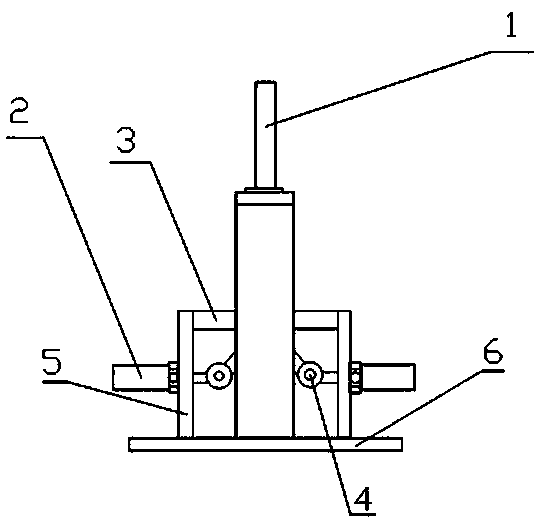
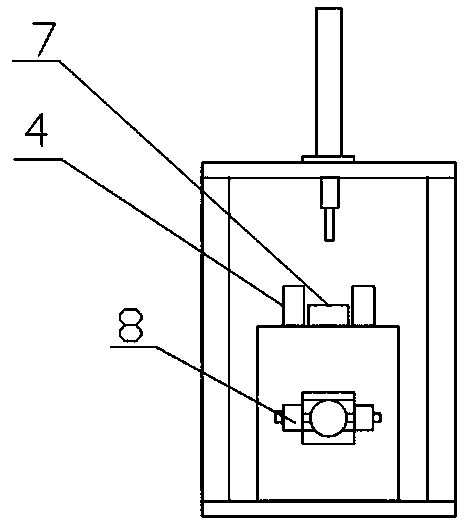
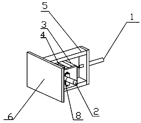
[0022] Example 1, such as Figure 1-3 , a double-ear type oil cylinder pouring riser removal machine, including a lower pressure cylinder 1, a side pressure cylinder 2, a workbench 3, a jaw 4, a cylinder support plate 5, a base plate 6, a riser runner mold 7, a hydraulic station, the center position of the base plate 6 is provided with a workbench 3, and the front and rear sides of the workbench 3 are respectively provided with side pressure cylinders 2, and the jaws 4 are arranged inside the workbench 3, and one end of the jaws 4 passes through the The outer wall of the workbench 3 is connected with the front and rear side pressure cylinders 2, and the other end of the jaw 4 passes through the outer wall of the workbench 3 and is arranged on both sides of the riser runner mold 7, and the riser runner mold 7 is located on the On the top of the workbench 3; the base plate 6 is provided with an oil cylinder support plate 5, and the top of the oil cylinder support plate 5 is fixe...

Embodiment 2

[0028] Example 2, such as Figure 1-3 , a double-ear type oil cylinder pouring riser removal machine, including a lower pressure cylinder 1, a side pressure cylinder 2, a workbench 3, a jaw 4, a cylinder support plate 5, a base plate 6, a riser runner mold 7, a hydraulic station, the center position of the base plate 6 is provided with a workbench 3, and the front and rear sides of the workbench 3 are respectively provided with side pressure cylinders 2, and the jaws 4 are arranged inside the workbench 3, and one end of the jaws 4 passes through the The outer wall of the workbench 3 is connected with the front and rear side pressure cylinders 2, and the other end of the jaw 4 passes through the outer wall of the workbench 3 and is arranged on both sides of the riser runner mold 7, and the riser runner mold 7 is located on the On the top of the workbench 3; the base plate 6 is provided with an oil cylinder support plate 5, and the top of the oil cylinder support plate 5 is fixe...


PUM


Abstract

The invention discloses a double-suspension-loop type oil cylinder casting head removing machine. The double-suspension-loop type oil cylinder casting head removing machine comprises a down-pressing oil cylinder, side-pressing oil cylinders, a working table, jaws, an oil cylinder supporting plate, a base plate, a casting head pouring gate model and a hydraulic station. The working table is arranged at the center of the base plate and the side-pressing oil cylinders are arranged at the front side and the rear side of the working table separately. The jaws are arranged in the working table. The ends of the jaws penetrate the outer wall of the working table and are connected with the front side-pressing oil cylinder and the rear side-pressing oil cylinder separately, and the other ends of the jaws penetrate the outer wall of the working table and are arranged at two sides of the casting head pouring gate model which is located on the working table. The oil cylinder supporting plate is arranged on the base plate and the down-pressing oil cylinder is fixedly supported at the top end of the oil cylinder supporting plate. The down-pressing oil cylinder and the side-pressing oil cylinder are connected with the hydraulic station separately. According to the machine, the rapid separation of the double-suspension-loop products can be realized, both time and labor can be saved, the quality of the products can be guaranteed, the labor intensity can be reduced and the the working efficiency can be improved by 3 to 4 times.

Description

technical field [0001] The invention belongs to the technical field of casting, and relates to a casting riser removing device, in particular to a special-shaped product whose casting is easy to crack and whose riser is difficult to separate from the casting. Background technique [0002] In the foundry industry, in order to filter slag avoidance and feed shrinkage, it is usually necessary to set up a sprue riser, but after cooling and forming, the sprue riser has completed its mission and becomes redundant scraps that must be removed. [0003] At present, the small double-ear product has a unique structure, and the sprue and the product are not easy to separate. In the past, it was knocked down with a manual hammer, which was easy to break the product, and the work efficiency was low. Later, a kind of hydraulic pliers was developed, which replaced the knocking of hand hammers, and the labor intensity was reduced, but the work efficiency was not good. The hydraulic jaws were...

Claims


Application Information

Patent Timeline
Patent Type & Authority Patents(China)
IPC IPC(8): B22D31/00
CPCB22D31/00
Inventor 张永志
Owner 临沂市鲁蒙水表制造有限公司
Why Eureka
Try Eureka