Casting head removing machine

A technology for pouring risers and oil cylinders, which is applied in the field of iron cap pouring riser removal equipment, can solve the problems of difficult processing of large parts, high labor intensity, and harmfulness to the human body, and achieves the solution of hammering difficulties, labor intensity, and simple structure practical effect

Inactive Publication Date: 2016-11-09
临沂市鲁蒙水表制造有限公司
View PDF8 Cites 1 Cited by
  • Summary
  • Abstract
  • Description
  • Claims
  • Application Information

AI Technical Summary

Problems solved by technology

[0003] At present, the method of removing and separating the risers of larger iron cap products is to use manual hammering. This method is inefficient, labor-intensive, and has a lot of dust, which is harmful to the human body. It is difficult to process large pieces. Workers are greatly restricted, and it also causes certain difficulties in management. Its labor intensity is unacceptable to most people.

Method used


Image

  • Casting head removing machine
  • Casting head removing machine
  • Casting head removing machine

Examples


Embodiment 1

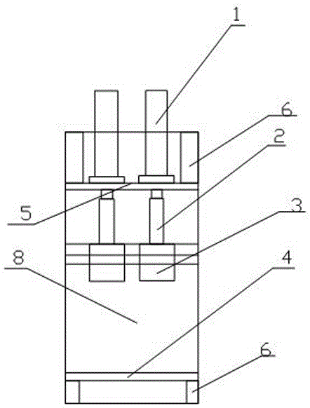
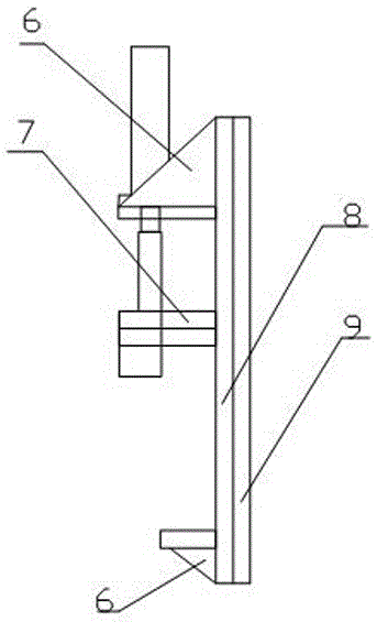
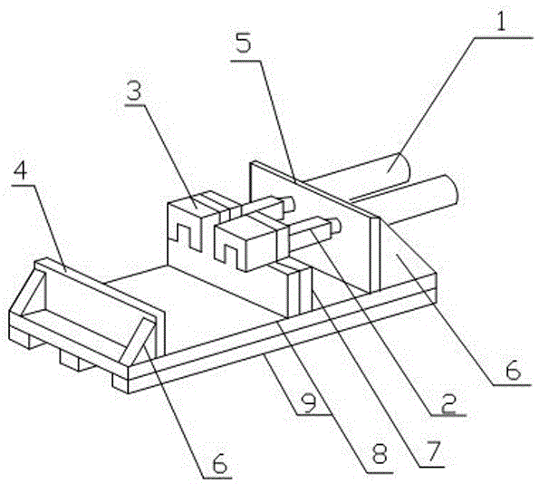
[0022] Example 1, such as Figure 1-3 , a pouring riser removal machine is characterized in that it includes an oil cylinder 1, a push rod 2, a push rod guide sleeve 3, a blank backing plate 4, an oil cylinder support plate 5, a blank rear support plate 7, a bottom plate 8, and the oil cylinder 1 Supported by the oil cylinder support plate 5, the oil cylinder support plate 5 is fixed on the upper end of the bottom plate 8, and the lower part of the oil cylinder support plate 5 is provided with the ejector rod 2 which is connected to the oil cylinder 1, and the ejector rod 2 is inserted into the ejector rod guide sleeve 3 for fixing. And the ejector pin guide sleeve 3 is fixed on one side of the blank back spreader 7 , the other side of the blank back spreader 7 is fixed on the middle end of the bottom plate 8 , and the blank backing plate 4 is fixed on the bottom end of the bottom plate 8 .

[0023] Further preferably, the number of said cylinders 1, ejector rods 2, and ejecto...

Embodiment 2

[0028] Example 2, such as Figure 1-3 , a pouring riser removal machine is characterized in that it includes an oil cylinder 1, a push rod 2, a push rod guide sleeve 3, a blank backing plate 4, an oil cylinder support plate 5, a blank rear support plate 7, a bottom plate 8, and the oil cylinder 1 Supported by the oil cylinder support plate 5, the oil cylinder support plate 5 is fixed on the upper end of the bottom plate 8, and the lower part of the oil cylinder support plate 5 is provided with the ejector rod 2 which is connected to the oil cylinder 1, and the ejector rod 2 is inserted into the ejector rod guide sleeve 3 for fixing. And the ejector pin guide sleeve 3 is fixed on one side of the blank back spreader 7 , the other side of the blank back spreader 7 is fixed on the middle end of the bottom plate 8 , and the blank backing plate 4 is fixed on the bottom end of the bottom plate 8 .

[0029] Further preferably, the number of said cylinders 1, ejector rods 2, and ejecto...


PUM


Abstract

The invention discloses a casting head removing machine. The casting head removing machine comprises oil cylinders, ejector rods, ejector rod guide sleeves, a workblank backup plate, an oil cylinder supporting plate, a workblank rear supporting plate and a base plate. The oil cylinders are supported by the oil cylinder supporting plate. The oil cylinder supporting plate is fixed to the upper end of the base plate. The ejector rods which are movably connected with the oil cylinders are arranged on the lower portion of the oil cylinder supporting plate. The ejector rods are inserted into the ejector rod guide sleeves to be fixed, and the ejector rod guide sleeves are fixed to one side of the workblank rear supporting plate. The other side of the workblank rear supporting plate is fixed to the middle end of the base plate. The workblank backup plate is fixed to the bottom end of the base plate. The casting head removing machine solves the problem of being difficult to hammer, labor intensity is relieved thoroughly, the work efficiency is more than three times of original work efficiency, and product quality is stable.

Description

technical field [0001] The invention belongs to the technical field of casting, and in particular relates to an extra-large type iron cap-like pouring riser removal equipment. Background technique [0002] In the foundry industry, in order to filter slag avoidance and feed shrinkage, it is usually necessary to set up a sprue riser, but after cooling and forming, the sprue riser has completed its mission and becomes redundant scraps that must be removed. [0003] At present, the method of removing and separating the risers of larger iron cap products is to use manual hammering. This method is inefficient, labor-intensive, and has a lot of dust, which is harmful to the human body. It is difficult to process large pieces. Workers are greatly restricted, and it also causes certain difficulties in management. Its labor intensity is unacceptable to most people. [0004] Therefore, in view of the above-mentioned technical problems, it is necessary to provide a sprue riser removal ...

Claims


Application Information

Patent Timeline
Patent Type & Authority Applications(China)
IPC IPC(8): B22D31/00
CPCB22D31/00
Inventor 张永志
Owner 临沂市鲁蒙水表制造有限公司
Why Eureka
Try Eureka