Magnectic-conductive member end-part defect detection device

A defect detection and component technology, applied in the direction of material magnetic variables, etc., can solve the problems of difficult automatic detection, easy diffusion of magnetic field, complex mechanism and other problems, and achieve the effect of strong anti-interference ability, low labor intensity and flexible scanning mode

Inactive Publication Date: 2003-03-26
HUAZHONG UNIV OF SCI & TECH
View PDF0 Cites 7 Cited by
  • Summary
  • Abstract
  • Description
  • Claims
  • Application Information

AI Technical Summary

Problems solved by technology

However, the magnetic flux leakage detection method has not been used to detect the end defect of the magnetic conductive member. This is because the magnetic field is easy to diffuse when the end is magnetized, and the shape of the end is special, the realization mechanism is complicated, and it is difficult to realize automatic detection. Treat the end as the difficulty and blind spot of inspection

Method used


Image

  • Magnectic-conductive member end-part defect detection device
  • Magnectic-conductive member end-part defect detection device
  • Magnectic-conductive member end-part defect detection device

Examples


Embodiment Construction

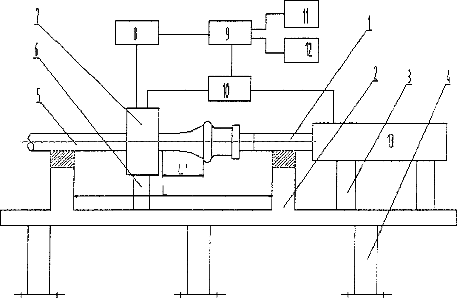
[0020] Such as figure 1 As shown, the whole device is mainly composed of auxiliary guide rod (1), magnetizer (2), detection probe (7), signal acquisition and preprocessor (8), signal processor (9), controller (10), scanning Drive mechanism (13) and display (11) printer (12) and necessary support (3), (4), (6) form. figure 1 (3) is used to support the scanning drive mechanism (13), (4) is used to support the whole system, and the whole device is fastened on the ground with expansion bolts, and (6) is used to support the detection probe (7). The magnetizer (2) is composed of an excitation source and an armature. The permanent magnet steel is used as the excitation source, and the beam in the device is used as a magnetically conductive armature to form a magnetic field when in contact with the guide rod (1) and the component under test (5). way to magnetize them. Depending on the cross-sectional area of ​​the measured component (5), 2 to 50 pairs of magnetic steels can be selec...


PUM


Abstract

A testing device for magnetic conductive components terminal defect resolves the problem of terminal blind zone by ordinary magnet leakge method. The device includes a test part and signal processing part in which two magnetic poles of the magnetizer, test probee and assistant guide rod of the test part are at the same shaft line. The structure of the test probe is a two stage clamping structure in which the first comprises a shell, a spread spring, a holddown and the second has a reed, a detector, Hall units and magnetic focusing plate, the signal process part contains a preprocessor, signal processer, a display and a controller. The assistant guide rod resolves problem of blind zone at the terminal.

Description

technical field [0001] The invention belongs to detection equipment, in particular to a device for detecting defects in magnetically conductive components using the principle of magnetic flux leakage detection. Background technique [0002] In the detection of magnetic components such as sucker rods, drill pipes, oil pipes, and steel rods, the end detection is an important and difficult point. During the use of components, the end is the part of the connection between components, which is subjected to complex forces and is most prone to defects such as cracks, corrosion, and wear. The main detection method used at present is still the magnetic particle detection method (see Wu Zezhong, Li Jingwen, Zhao Xuesheng, etc. "Rod Pumping Equipment and Technology" Petroleum Industry Press 1994.10.P395-396). Both magnetic particle testing and magnetic flux leakage testing belong to magnetic testing methods, and both use the leakage magnetic field at the defect to detect after magneti...

Claims


Application Information

Patent Timeline
Patent Type & Authority Applications(China)
IPC IPC(8): G01N27/82
Inventor 程顺峰康宜华武新军
Owner HUAZHONG UNIV OF SCI & TECH
Why Eureka
Try Eureka