A main and standby equipment intelligent converter

A technology for backup equipment and converters, applied in instruments, simulators, general control systems, etc., can solve problems such as increased labor intensity of workers, untimely equipment switching, economic damage to working equipment, etc., to reduce labor costs and labor intensity of workers. , maintain and prevent equipment aging, and ensure the effect of normal and safe operation

Inactive Publication Date: 2015-09-23
梁超洪 +4
View PDF8 Cites 7 Cited by
  • Summary
  • Abstract
  • Description
  • Claims
  • Application Information

AI Technical Summary

Problems solved by technology

First of all, the manual switching method requires special operators to be on duty for a long time during the production and work process, which not only increases the labor intensity of the workers, but also increases the labor cost of the production and operation of the enterprise
Secondly, due to the negligence of workers and other reasons, the manual operation method is prone to problems such as untimely switching of equipment, lagging behind, etc., resulting in damage to working equipment and economic losses
Finally, the manual switching method is difficult to switch between the main and backup equipment on time, resulting in the main equipment working for a long time and shortening the service life of the equipment. If the standby equipment is out of service for too long, it is prone to motor dampness, poor insulation, deterioration of lubricating oil, Mechanical jamming, valve rust and other phenomena, accidents such as abnormal operation often occur during emergency switching, causing very large economic losses to the production and work of enterprises and individuals

Method used


Image

  • A main and standby equipment intelligent converter
  • A main and standby equipment intelligent converter
  • A main and standby equipment intelligent converter

Examples


Embodiment Construction

[0028] In order to facilitate those skilled in the art to better understand the essence of the present invention, the specific implementation manners of the present invention will be described in detail below in conjunction with the accompanying drawings.

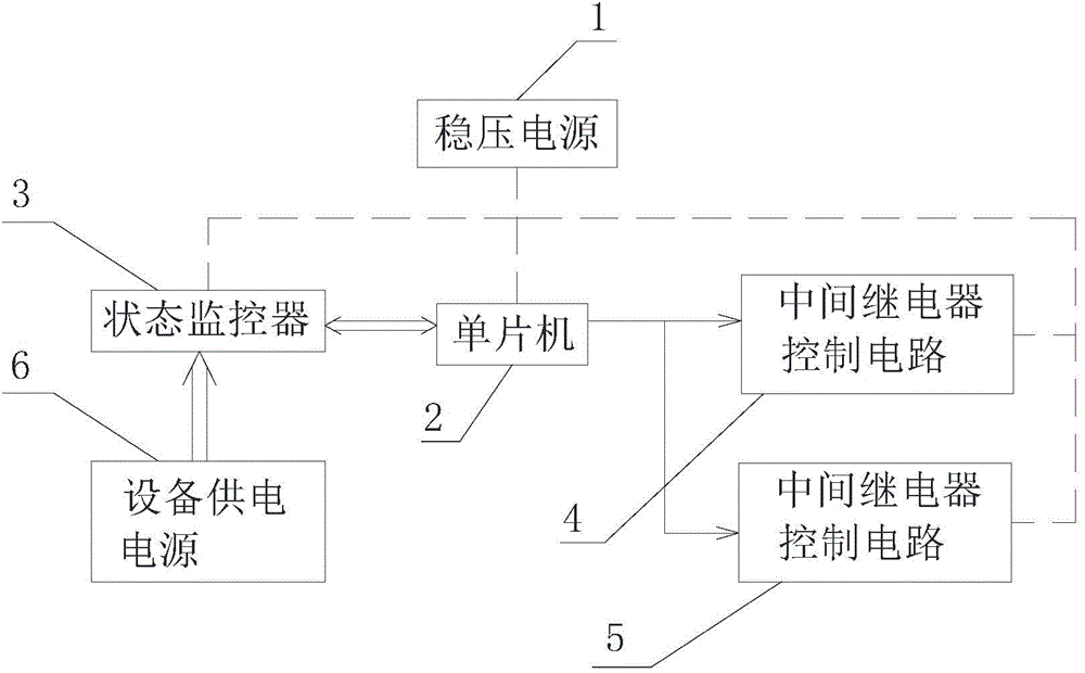
[0029] Such as figure 1 As shown, an intelligent converter for main and backup equipment includes: a regulated power supply 1 , a single chip microcomputer 2 , a state monitor 3 , an intermediate relay control circuit 4 and an intermediate relay control circuit 5 .

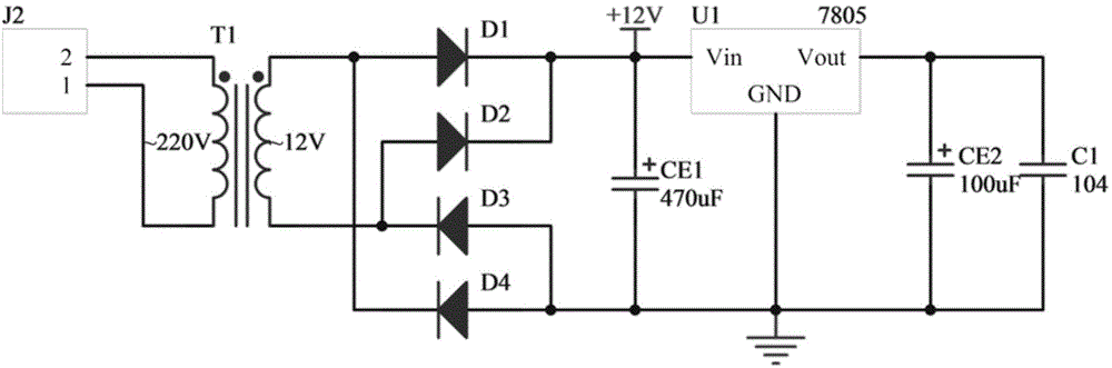
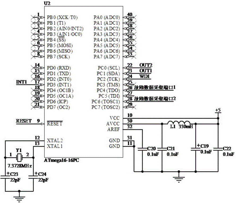
[0030] Among them, the regulated power supply 1 provides a stable voltage for the single-chip microcomputer 2, the status monitor 3 and the intermediate relay control circuits 4, 5. The state monitor 3 mainly ensures the safe and stable operation of the control program of the single-chip microcomputer 2 , monitors the operation status of the power supply 6 of the equipment, and feeds fault information to the single-chip microcomputer 2 . The single-chip microc...


PUM


Abstract

The invention discloses a main and standby equipment intelligent converter including a DC stabilized voltage supply, a state monitor, a single-chip microcomputer and an intermediate relay output control circuit. The DC stabilized voltage supply of the intelligent converter provides a stable working voltage for the intermediate relay output control circuit and a single-chip microcomputer circuit; an input terminal of the intermediate relay output control circuit is in series connection with an output interface of the single-chip microcomputer; an output terminal of the intermediate relay output control circuit is connected to an equipment switch circuit; the single-chip microcomputer obtains equipment fault trigger signals, timed trigger signals and power-off trigger signals in real time to control connection of different contacts of two intermediate relay output circuits so as to further control working state switching between main and standby equipment and realize fault switching, timed switching and power-off switching between the main and the standby equipment; phenomena that the main and the standby equipment can not be used due to fault and aging resulted from being unused for a long time are prevented; and normal and safe operation of the equipment are guaranteed.

Description

technical field [0001] The invention is a converter that uses a single-chip microcomputer to realize the switching of working states between devices, and belongs to the innovative technology in the field of intelligent converters Background technique [0002] In the actual production and work process of an enterprise, the important working equipment adopts the "one master and one backup" mode, and is equipped with a work switch. When one device fails, the work can be switched to another through the work switch. on a perfect device. At present, the switching between devices all adopts the mode of manually operating a switching switch. First of all, the manual switching method requires special operators to be on duty for a long time during the production and work process, which not only increases the labor intensity of the workers, but also increases the labor cost of the production and operation of the enterprise. Secondly, the manual operation method is prone to problems s...

Claims


Application Information

Patent Timeline
Patent Type & Authority Applications(China)
IPC IPC(8): G05B19/042
CPCG05B19/042G05B2219/25341
Inventor 梁超洪李秀忠何权昌欧幸福陈思涛
Owner 梁超洪
Why Eureka
Try Eureka