A jig for machining an electric wheel hub

A technology of electric vehicles and wheel hubs, which is applied in the direction of manufacturing tools, metal processing equipment, metal processing machinery parts, etc., can solve the problems of low clamping efficiency, inconvenient clamping, and high labor intensity of workers, so as to improve work efficiency and save energy. the effect of time

Active Publication Date: 2018-03-23
徐州顺达钢轮制造有限公司
View PDF12 Cites 0 Cited by
  • Summary
  • Abstract
  • Description
  • Claims
  • Application Information

AI Technical Summary

Problems solved by technology

When the electric wheel hub is processed by the existing technology, the clamping of the wheel hub often needs to be completed manually. This processing method has the problems of high labor intensity, inconvenient clamping and low clamping efficiency, which improves the processing of electric vehicles. Therefore, there is an urgent need to improve the clamping technology to reduce costs and improve work efficiency. For example, the patent CN 203304601 U discloses a clamp for processing the front wheel hub of an electric vehicle, and the patent CN203304922 U discloses a clamp for processing the rear hub of an electric vehicle. Fixtures, in the two patents, the front and rear hubs of the electric vehicle are clamped by setting the chuck connecting disc, positioning disc, clamping claw, clamping block and cylinder. These two clamping methods are only through the axis of the hub And clamp the edge of the hub, although the predetermined effect can be achieved, but when the processing is subjected to external force, the hub is easy to arch and break away from the chuck connection plate, so that the position of the hub is shifted, resulting in the stop of processing and reducing the working efficiency of processing , wastes time, and easily damages the hub

Method used


Image

  • A jig for machining an electric wheel hub

Examples


Embodiment Construction

[0014] The following will clearly and completely describe the technical solutions in the embodiments of the present invention with reference to the accompanying drawings in the embodiments of the present invention. Obviously, the described embodiments are only some, not all, embodiments of the present invention. Based on the embodiments of the present invention, all other embodiments obtained by persons of ordinary skill in the art without making creative efforts belong to the protection scope of the present invention.

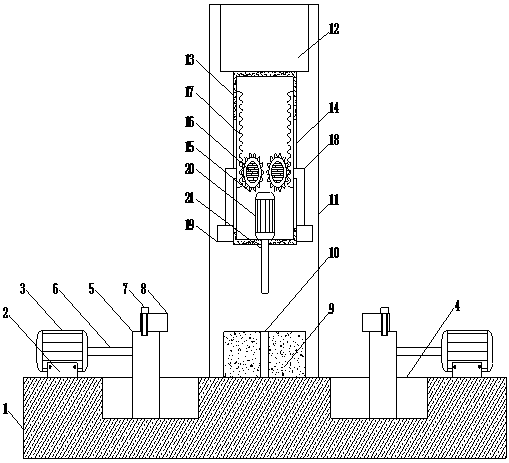
[0015] Such as figure 1 As shown in the figure, a jig for processing electric wheel hubs includes a console 1, and both sides of the top of the console 1 are connected with a first hydraulic cylinder 3 through a fixing seat 2, and a screw is used between the fixing seat 2 and the first hydraulic cylinder 3 fixed to make the structure more stable, two limit grooves 4 are provided on the top of the console 1, and the two limit grooves 4 are located between the t...


PUM


Abstract

The invention discloses an excellent-clamping-function clamp for electric vehicle hub processing. The excellent-clamping-function clamp comprises an operating table. First hydraulic cylinders are connected to the two sides of the top of the operating table through fixing bases, two limiting grooves are formed in the top of the operating table and located between the two first hydraulic cylinders, sliding blocks are connected in the limiting grooves and connected with the first hydraulic cylinders through first hydraulic rods, annular clamping bases are connected to the tops of the sliding blocks through bolts, a circular truncated cone is connected to the top of the operating table and located between the two limiting grooves, a hole groove is formed in the center of the top of the circular truncated cone, and a vertical beam is connected on the operating table and located on the back side of the circular truncated cone. The clamp has the excellent clamping function, and protrusions, caused by shaking, of a hub can be avoided; hub position skewing caused when the hub is separated from the circular truncated cone is avoided, stopping in the processing process is avoided, the working efficiency of processing is improved, time is saved, and it is guaranteed that the hub can not be damaged.

Description

technical field [0001] The invention relates to the technical field of processing electric vehicle accessories, in particular to a jig for processing electric wheel hubs. Background technique [0002] Electric vehicles, that is, electric drive vehicles, have another name called electric drive vehicles. Electric vehicles are divided into AC electric vehicles and DC electric vehicles. Generally speaking, an electric vehicle uses a battery as an energy source, and converts electrical energy into mechanical energy through components such as a controller and a motor to control the current and change the speed of the vehicle. After more than ten years of development, electric vehicles have become the most common means of transportation in the streets and alleys, and are also the most well-known green tools. Moreover, the structure of the electric vehicle is simple, cheap, economical and practical, and the parts on the electric vehicle are also very easy to configure, such as the...

Claims


Application Information

Patent Timeline
Patent Type & Authority Patents(China)
IPC IPC(8): B23Q3/08
CPCB23Q3/062B23Q3/082B23Q2703/04
Inventor 金文雅
Owner 徐州顺达钢轮制造有限公司
Why Eureka
Try Eureka