Long-endurance flexible wing controllable platform

A flexible-wing, long-endurance technology, applied in the field of flexible-wing platforms, can solve the problems of poor autonomous flight ability and lack of platform control, and achieve the effect of good controllability

Active Publication Date: 2016-11-09
GENERAL ENG RES INST CHINA ACAD OF ENG PHYSICS
View PDF6 Cites 10 Cited by
  • Summary
  • Abstract
  • Description
  • Claims
  • Application Information

AI Technical Summary

Problems solved by technology

[0002] Traditional flexible wing platforms mainly include flexible wings, airframes, etc. Among them, the flexible wing, as a mechanism for generating lift, can be divided into round umbrella and parafoil. Poor, the parafoil has the function of controlling the platform, but its actuator, that is, the steering gear, needs to pull the paracord, and the general layout is relatively large. For platforms with size restrictions, the contradiction between size constraints and autonomous flight is difficult to solve

Method used


Image

  • Long-endurance flexible wing controllable platform
  • Long-endurance flexible wing controllable platform
  • Long-endurance flexible wing controllable platform

Examples


Embodiment 1

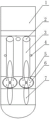
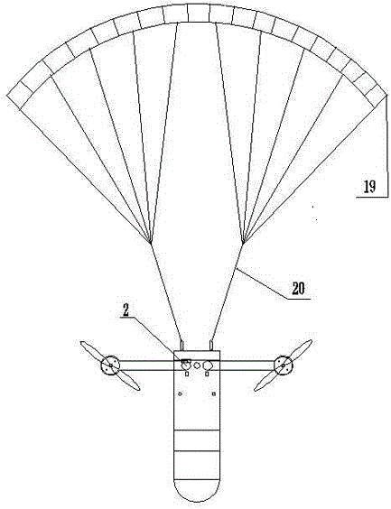
[0025] like figure 1 , figure 2 , image 3 , Figure 4 The shown long-endurance flexible wing controllable platform includes a cylindrical body 1 and a flexible parafoil 19, the body 1 includes an umbrella compartment 9 that can be separated from the body under the control of the flight control system, and the flexible parafoil 19 is in front of the umbrella. In the umbrella cabin 9 and connected to the body 1 through the paracord 20; the paracord 20 and the body can be connected by the eyebolt 11;

[0026] The body is provided with a cut surface 22, and the cut surface 22 is provided with two power arms 3, a fixed structure 4 for folding and limiting the power arms 3, and the drive power arms are unfolded and the two power arms are unfolded on a straight line. Rotating mechanism 2 for locking the power arm;

[0027] The distal end of the power arm 3 is provided with a motor 6 controlled by the flight control system and a propeller 7 which rotates under the drive of the m...

Embodiment 2

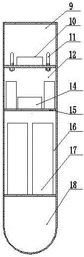
[0031] like figure 1 , figure 2 As shown in the figure, the structure of the body of this embodiment is improved on the basis of the above-mentioned embodiment, that is, the body includes a top-down umbrella cabin, a flight control cabin 12, a power cabin 16 and a load cabin 18, and two adjacent cabins They are separated by a partition plate 15 with holes. The flight control system is set in the flight control cabin, and the power cabin is set with a power system that provides electrical energy for the flight control system and other electronic devices such as loads. The arrangement of holes on the partition plate facilitates the arrangement of wiring between systems.

[0032] The flight control system is connected to the power system 17 and the signal receiving system. The signal receiving system includes a GPS antenna 10 and a data link antenna. The signal receiving system is placed in the parachute.

[0033] like image 3 As shown, the rotation mechanism 21 includes a...


PUM


Abstract

The invention discloses a long-endurance flexible wing controllable platform which comprises a machine body and a flexible parafoil. The machine body comprises a parafoil cabin capable of being separated from the machine body under the control of a flight control system. The flexible parafoil is arranged in the parafoil cabin before being expanded and connected to the machine body through parafoil ropes. The machine body is provided with a tangent plane which is provided with two power arms, fixing structures for folding and limiting the power arms and rotating mechanisms driving the power arms to be expanded and locking the power arms when the two power arms are expanded to one straight line. The far end of each power arm is provided with a motor controlled by the flight control system and a propeller driven by the motor to rotate. The long-endurance flexible wing controllable platform has relatively good controllability, the double motors of the power arms are under differential motion control to supply steering capacity to the platform, and autonomous flight of the platform is achieved.

Description

technical field [0001] The invention relates to the field of flexible wing platforms, in particular to a long-endurance flexible wing controllable platform that is capable of autonomous flight, suitable for bomb-loaded delivery and long-duration airborne. Background technique [0002] The traditional flexible wing platform mainly includes flexible wings, body, etc. Among them, the flexible wings are the mechanism for generating lift, which can be divided into round umbrella and parafoil. Poor, the parafoil has the function of controlling the platform, but its actuator, that is, the steering gear, needs to pull the parachute rope, which is generally arranged in a large size. For platforms with size restrictions, the contradiction between size constraints and autonomous flight is difficult to solve. SUMMARY OF THE INVENTION [0003] In order to solve the above technical problems, the present invention provides a long-endurance flexible wing controllable platform. [0004] T...

Claims


Application Information

Patent Timeline
Patent Type & Authority Applications(China)
IPC IPC(8): B64C27/08B64D17/80B64C39/00
CPCB64C27/08B64C39/00B64D17/80B64U10/00B64U10/50B64U30/20
Inventor 卢永刚邓坤钱立新孙传杰朱永清陈伟周婕群
Owner GENERAL ENG RES INST CHINA ACAD OF ENG PHYSICS
Why Eureka
Try Eureka