
Embracing-type strapping machine

A strapping machine and machine head technology, applied in the field of wrapping strapping machines, can solve the problems of inconvenient manual operation, high investment cost, large strapping machine body, etc., and achieve simple strapping action process, low equipment investment cost, simple and light structure Effect

Active Publication Date: 2016-11-09
江阴瑞特泰科包装设备有限公司
View PDF8 Cites 2 Cited by
  • Summary
  • Abstract
  • Description
  • Claims
  • Application Information

AI Technical Summary

Problems solved by technology

[0003] However, due to the uncertainty of the on-site installation form and site of the baler, it also brings great limitations to the installation space of the fully automatic strapping machine that is currently equipped on the baler, which is not conducive to the installation of those strapping machines in the form of traditional guide rails.
When the guide rail is installed on the front and rear sides of the main press of the baler, it is easy to interfere with the baler track. The strapping machine track cannot be installed
Even if it can be installed, the strapping machine is waiting outside the main pressure column of the strapping machine, occupying the original manual operation space of the strapping machine, and occupying the safe area and passageway for workers to operate, which brings great inconvenience to manual operation
Moreover, the body of the strapping machine that uses guide rails to move is relatively large, the structure is relatively complicated, and the input cost is relatively high.
[0004] In addition, since most of the installed hydraulic balers did not consider the demand for automatic tying at that time, it was difficult to realize the user's request to install a traditional full-automatic baling machine due to design and site constraints.

Method used


Image

  • Embracing-type strapping machine
  • Embracing-type strapping machine
  • Embracing-type strapping machine

Examples


Embodiment Construction

[0023] The technical solutions of the present invention will be further described below in conjunction with the accompanying drawings and through specific implementation methods.

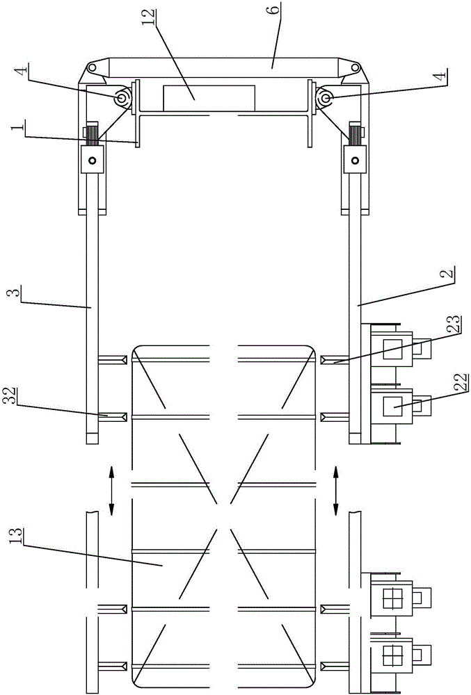
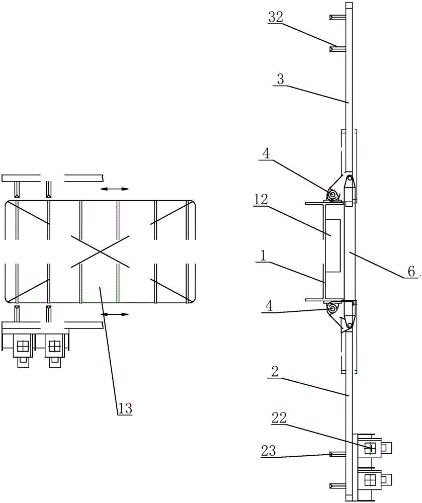
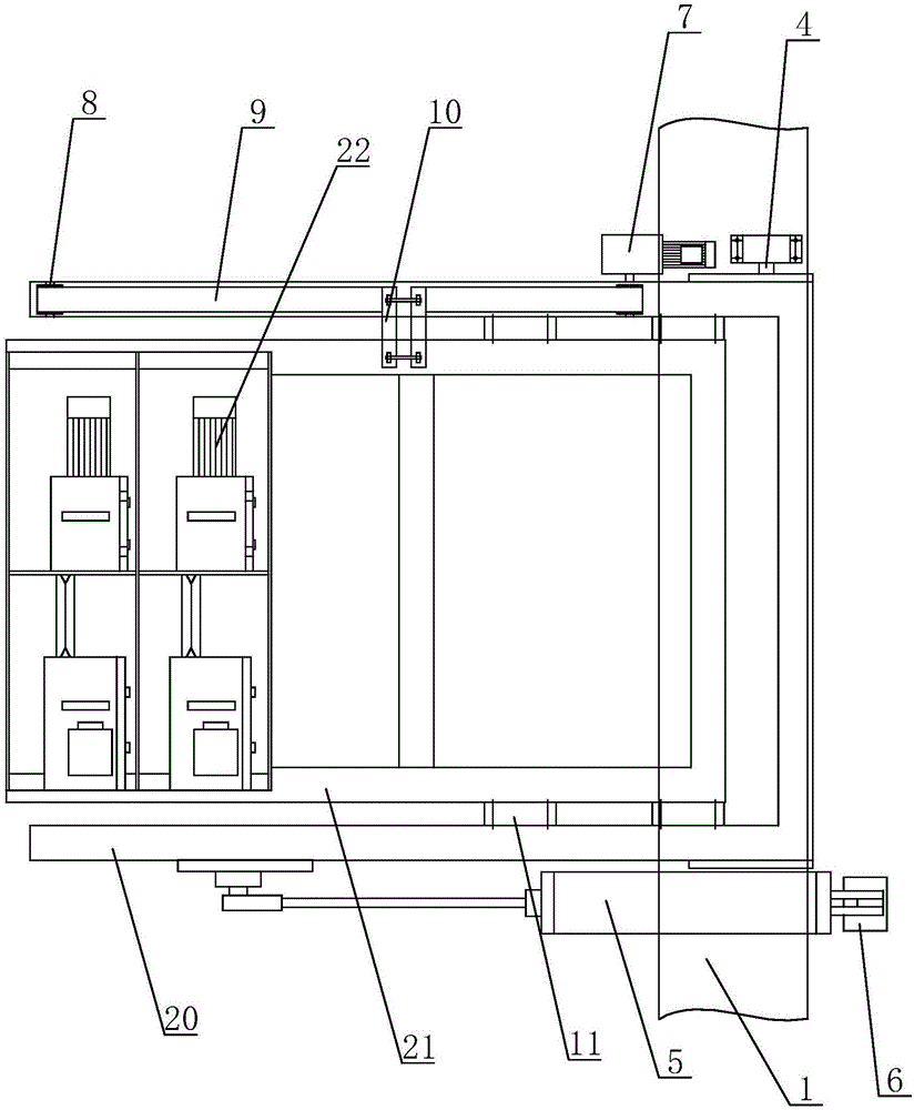
[0024] see Figure 1 to Figure 4 As shown, in this embodiment, a kind of embracing strapping machine includes the main pressure column 1 of the baler, that is, the column of the original baler is used as the base, and the two sides of the main pressure column 1 of the baler are correspondingly hinged with a strapping unit 2 And the belt guide unit 3, the strapping unit 2 includes the first rotating frame 20 hinged on one side of the main pressure column 1 of the packing machine through the rotating shaft 4, and the first rotating frame 20 is provided with a Sliding first sliding bracket 21, the front end of the first sliding bracket 21 is provided with two strapping heads 22 at intervals, and the strapping head 22 is arranged on the first rotating frame 20 in cooperation with the strapping head 22. ...


PUM


Abstract

The invention discloses an embracing-type strapping machine. The embracing-type strapping machine comprises a vertical post, wherein a strapping unit and a belt guiding unit are correspondingly hinged to two sides of the vertical post; the strapping unit comprises a first rotary rack; at least one strapping machine head is arranged on the first rotary rack; the belt guiding unit comprises a second rotary rack; at least one belt guiding device component corresponding to the at least one strapping machine head is arranged on the second rotary rack; the first rotary rack and the second rotary rack are separately arranged on the vertical post through a rotary shaft; and the first rotary rack and the second rotary rack are separately connected with a rotation driving device for driving the first rotary rack and the second rotary rack to rotate. By adopting the above embracing-type strapping machine, a certain ground space is not occupied; at an initial position, an on-site safety passage is not occupied, and the embracing-type strapping machine can serve as a safety guard railing, so that workers are prevented from entering a hydraulic packing machine dangerous area; the strapping action process is simple; the structure is light and handy; equipment investment cost is low; and assembly is convenient.

Description

technical field [0001] The invention belongs to the packing and bundling technology of articles, in particular to an embracing bundling machine for automatically bundling packed articles. Background technique [0002] The development and application of fully automatic strapping machines in the compression and packaging of fluffy materials has been going on for some time. The fluffy materials such as fibers, waste, waste clothes, PET bottles, waste paper, etc. At present, the traditional baler structure suitable for fluffy materials is basically a double-box rotary hydraulic baler. In order to avoid the interference when the double boxes are rotated in the matching use of the strapping machine and the hydraulic baler, the strapping machine is generally arranged outside the column on the main pressure side of the strapping machine (traditionally, this side is a safe passage), and the strapping machine moves horizontally during work. Bundling is carried out on the package comp...

Claims


Application Information

Patent Timeline
IPC IPC(8): B65B13/04
CPCB65B13/04
Inventor 赵红虎石乐平
Owner 江阴瑞特泰科包装设备有限公司
Learn More