A grabbing device for a palletizer

A grasping device and stacker technology, applied in conveyors, manipulators, stacking of objects, etc., can solve the problems of decoupling, large space occupied by the claw body, falling buckets, etc., and achieve the effect of avoiding damage and saving space.

Active Publication Date: 2018-06-15
BEIJING AREOSTANARD NEW TECH +1
View PDF7 Cites 0 Cited by
  • Summary
  • Abstract
  • Description
  • Claims
  • Application Information

AI Technical Summary

Problems solved by technology

The patent adopts the method of hooking the edge of the barrel, and the cylindrical barrel is easy to shake during the movement, and accidents such as decoupling and falling of the barrel are prone to occur; moreover, most of the clamping positions of the claw body are in rigid contact with the cylindrical barrel, even if the contact part is designed with nylon, Flexible transition pieces such as rubber, but due to the large clamping force, it is easy to cause the deformation of the barrel, the paint surface of the barrel wall falls off, and other problems that damage the appearance of the cylindrical barrel; The front claws of the cylindrical barrel need to be opened at a certain angle. This method makes the claws take up a lot of space. In the case of grabbing multiple barrels at the same time, it is easy to cause interference between the claws

Method used


Image

  • A grabbing device for a palletizer
  • A grabbing device for a palletizer
  • A grabbing device for a palletizer

Examples


Embodiment 1

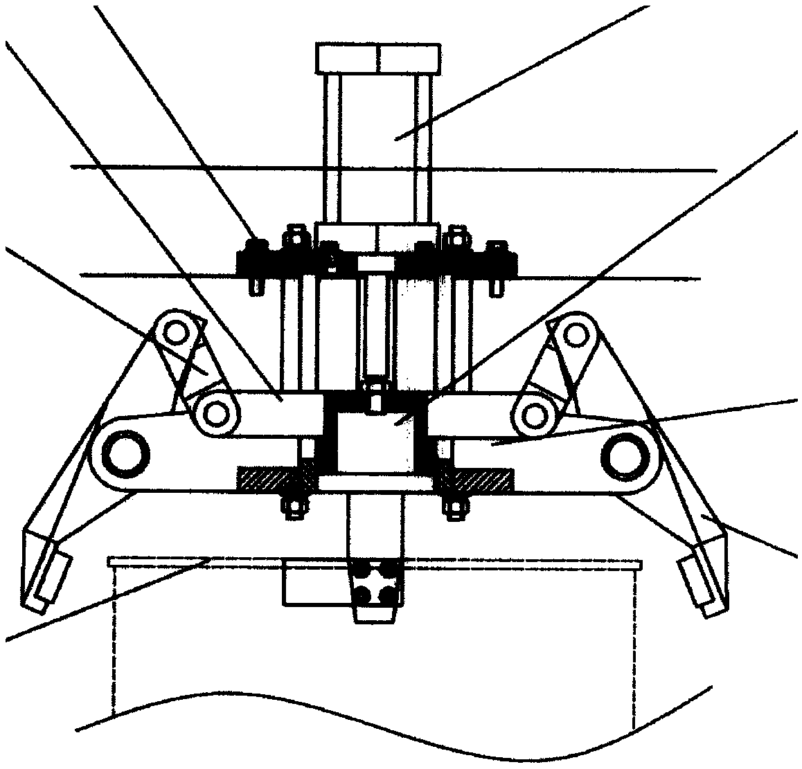
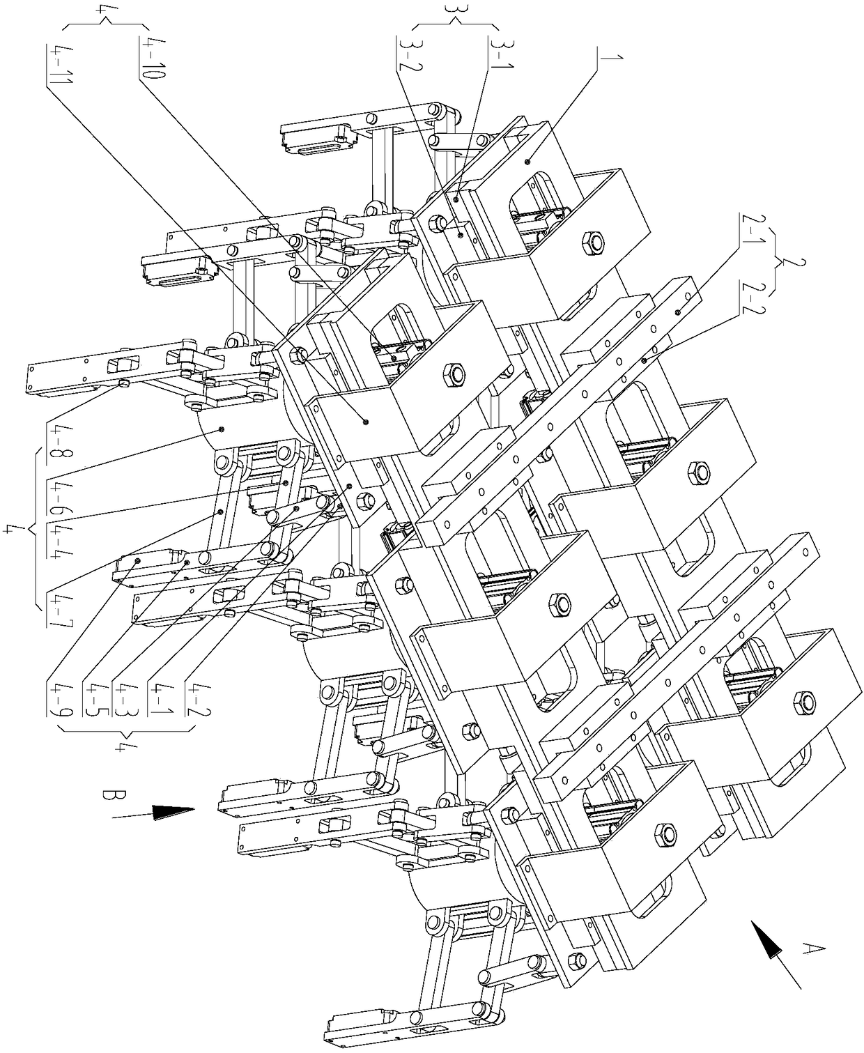
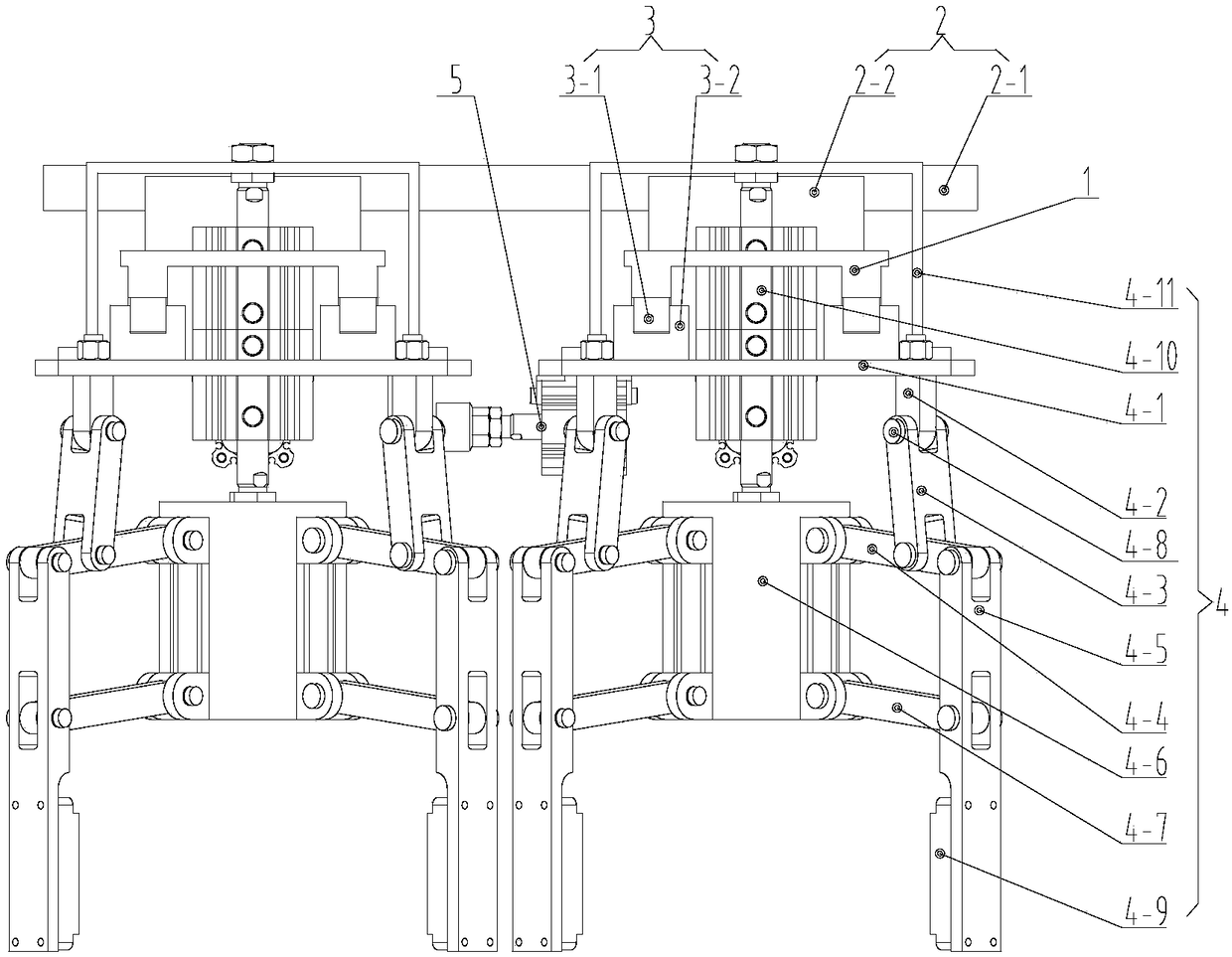
[0034] Such as image 3 , Figure 4 and Figure 5 As shown, before grabbing the cylinder barrel 6 whose diameter is X, the two cylinder rods of the grab cylinder 4-10 are all stretched out, and the claw body 4-5 goes deep into a certain position vertically along the periphery of the cylinder barrel 6, and the distance adjustment cylinder 5 The cylinder rods are all stretched out, so that the spacing of the grasping group 4 is consistent with the spacing of the cylinder barrel 6; as Figure 6 As shown, when grabbing, grabbing one of the cylinder rods of the cylinder 4-10 retracts (the drawing shows that the upper end cylinder rod retracts), and the sleeve frame 4-6 rises under the drive of grabbing the cylinder 4-10, by The parallelogram formed by the three-hole connecting rod 4-4, the claw body 4-5, the sleeve frame 4-6, and the two-hole connecting rod 4-7 is deformed, so that the claw body 4-5 moves to the middle and touches the cylindrical barrel 6 At the same time, the a...

Embodiment 2

[0036] Such as image 3 , Figure 7 and Figure 8 As shown, before grabbing the cylindrical barrel 7 with a diameter of Y (Y Figure 9 As shown, when grabbing, the two cylinder rods of the grabbing cylinder 4-10 are all retracted, and the sleeve frame 4-6 rises under the driving of the grabbing cylinder 4-10, and the three-hole connecting rod 4-4, claw The parallelogram formed by the body 4-5, the sleeve frame 4-6, and the two-hole connecting rod 4-7 is deformed, so that the claw body 4-5 moves to the middle and touches the edge of the cylinder barrel 7; meanwhile, the air bag 4-9 Inflate and clamp the cylindrical barrel 7, thereby completing a grab and getting ready for the stacking of the cylindrical barrel 7. After the palletizing was completed, the two cylinder rods of the grabbing cylinder 4-10 stretched out, the sleeve frame 4-6 descended, and the claw body 4-5 moved to the outside, while the air bag was deflated, and the grabbing device reset.

[0037] Illustrate a po...


PUM


Abstract

The invention discloses a gripping device of a stacker. The gripping device comprises supporting frames, heavy load mobile groups, light load mobile groups, gripping groups and distance adjusting air cylinders. Barrels are clamped through air bags, it is guaranteed that the cylindrical barrels do not swing in the gripping process, and the appearances of the barrels are prevented from being damaged; meanwhile, parallel four-bar mechanisms are used for the gripping device, jaws are perpendicular to one another all the time in the gripping process, and space is saved to the maximum degree. In addition, air cylinders for carrying out gripping actions are designed in two strokes, and the device can be compatible with two kinds of cylindrical barrels of different diameters.

Description

technical field [0001] The invention relates to palletizing equipment in the machinery industry, and specifically discloses a grabbing device for a palletizer, which is used to complete the grabbing and stacking of cylindrical barrels. Background technique [0002] Many liquid products produced in industry, such as lubricants, paints, coatings, etc., are packaged in cylindrical drums. In general, in order to facilitate transportation, cylindrical barrels need to be stacked on pallets in a certain order. During the stacking process, the grasping of cylindrical barrels is particularly critical. [0003] Existing grabbing devices generally realize grabbing by holding the bottom of the bucket or hooking the edge of the bucket. Using the method of holding the bottom of the bucket, when the claws go deep into the bottom of the bucket, it is easy to interfere with the pallet and the bucket cannot be placed, so it is rarely used in automatic palletizing equipment. [0004] Wang J...

Claims


Application Information

Patent Timeline
Patent Type & Authority Patents(China)
IPC IPC(8): B65G61/00B25J15/10
CPCB25J15/106B65G61/00B65G2201/0241
Inventor 徐国宝徐志刚杨红亮
Owner BEIJING AREOSTANARD NEW TECH
Why Eureka
Try Eureka