Molten iron desulfurization stirrer

A hot metal desulfurization and agitator technology, which is applied to mixers with rotating agitation devices, chemical instruments and methods, mixers, etc., can solve problems such as mechanical damage to slag removal, difficult processing and manufacturing, and wear on the bottom of the agitator. Reduce the retention effect and sticky slag speed, improve the stirring entrainment strength, and increase the effect of the effective area

Inactive Publication Date: 2016-11-09
武汉钢铁有限公司
View PDF8 Cites 0 Cited by
  • Summary
  • Abstract
  • Description
  • Claims
  • Application Information

AI Technical Summary

Problems solved by technology

At present, the main deficiencies in the use of the KR desulfurization agitator are: (1) Due to the existence of the forced vortex zone, during the use of the agitator, the desulfurizer (slag) involved in the molten iron accumulates at the angle between the blades in the center of the agitator , which not only affects the weight of the agitator and the agitation resistance, but also affects the agitation and entrainment cycle flow state of the desulfurizer, which deteriorates the dynamic conditions of agitation desulfurization and the technical and economic indicators of desulfurization; (2) The angle between the blades of the conventional KR agitator (90°) Smaller, the accumulation of desulfurization agent (slag) causes slag to stick to the surface of the refractory working lining in this area of ​​the agitator, and the operation of slag removal is difficult, and often the slag is not cleaned thoroughly, resulting in continuous deposition of sticky slag at the corners of the blades, and the slag is removed from the refractory working lining The mechanical damage is intensified, which affects the service life of the agitator, and further deteriorates the technical and economic indicators of molten iron stirring desulfurization; (3) During the use of the agitator, due to the increase in the speed, the agitator will shake to a certain extent, causing the agitator The relative movement between the bottom refractory material and the slag located in the forced vortex zone causes wear on the bottom of the agitator, further reducing the service life of the agitator
However, due to the complex structure of the agitator and the difficulty in processing and manufacturing, no industrial application reports have been seen so far.

Method used


Image

  • Molten iron desulfurization stirrer
  • Molten iron desulfurization stirrer
  • Molten iron desulfurization stirrer

Examples


Embodiment 1

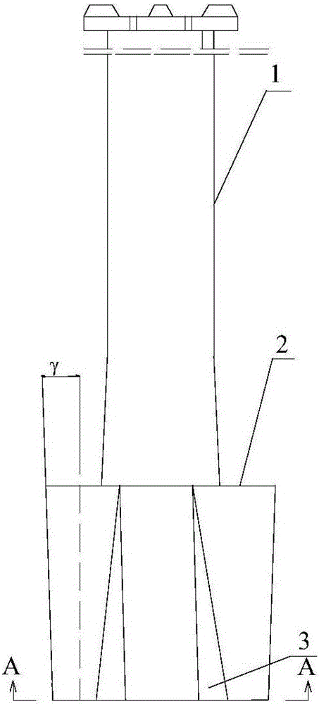
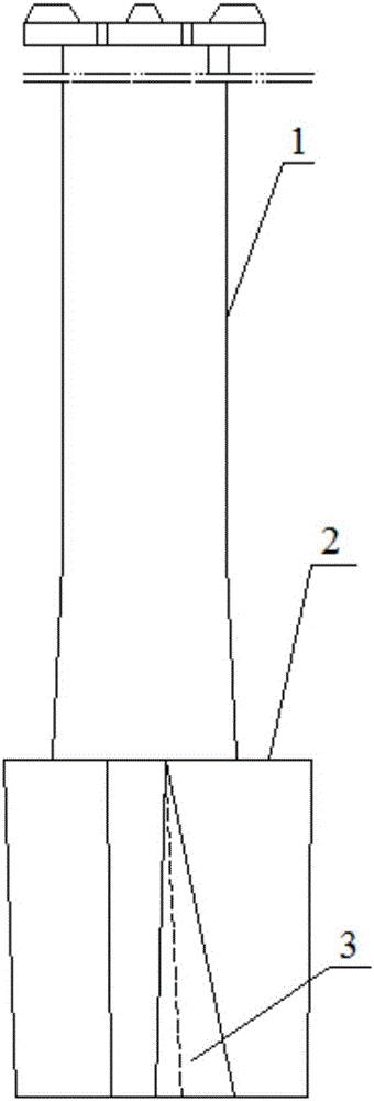
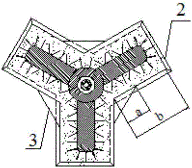
[0032] There are three stirring blades 2, which are evenly distributed in the circumferential direction around the rotating shaft 1. The outer surface of the stirring blade 2 is a slope that inclines radially outward at an angle γ from bottom to top, and γ is 2°. The water surface of the stirring blade 2 is clockwise. The direction is tilted forward by angle α from bottom to top, and the back iron water surface is a slope that tilts forward by angle β from bottom to top in a clockwise direction, and α is 6°, and β is 8°. The length of the stirring blade 2 is 50mm longer than that of the conventional stirring blade 2 . The guide body 3 is a triangular cone-shaped refractory material structure, and is cast together with the stirring blade 2; the common side length of the triangular bottom surface 8 of the guide body 3 and the stirring blade 2 is a, and the length of the stirring blade 2 is b, and a=0.4b.

Embodiment 2

[0034] There are four stirring blades 2, which are evenly distributed in the circumferential direction around the rotating shaft 1. The outer surface of the stirring blade 2 is a slope that inclines radially outward at an angle γ from bottom to top, and γ is 2°. The water surface of the stirring blade 2 is clockwise The direction is tilted forward by an angle α from bottom to top, and the back iron water surface is a slope that tilts forward by an angle β from bottom to top in a clockwise direction, and α is 8°, and β is 12°. The length of the stirring blade 2 is 50mm longer than that of the conventional stirring blade 2 . The guide body 3 is a slope-shaped refractory structure with a concave curved surface, and is cast together with the stirring blade 2; the common side length of the triangular bottom surface of the guide body 3 and the stirring blade 2 is a, and the length of the stirring blade 2 is b, and a=0.3b.


PUM


Abstract

The invention discloses a molten iron desulfurization stirrer. The molten iron desulfurization stirrer comprises a rotating shaft, and multiple stirring blades fixed on the outer peripheral edge of the rotating shaft and uniformly distributed in the peripheral direction of the rotating shaft; flow conductors are lined between two adjacent stirring blades, and are formed by surrounding triangular bottom surfaces and side surfaces outwards extending along each edge of the triangular bottom surfaces; one side surfaces of the flow conductors are bonded with the surfaces of one of two adjacent stirring blades; and the other side surfaces of the flow conductors are bonded with the surfaces of the other one of two adjacent stirring blades. The molten iron desulfurization stirrer is simple in structure and convenient for manufacturing, prominently improves the dynamic conditions of molten iron mechanical stirring desulfurization, prolongs the service life, and reduces the slag bonding between the stirring blades.

Description

technical field [0001] The invention belongs to the field of mechanical stirring and desulfurization of molten iron before converter steelmaking, and in particular relates to a molten iron desulfurization stirrer. Background technique [0002] KR (Kambara Reactor) stirring desulfurization method is a desulfurization technology outside the molten iron furnace that Nippon Steel began to study in 1963 and was applied to industrial production in 1965. This desulfurization method is based on a cross-shaped blade structure lined with refractory materials The agitator is immersed in the molten iron tank to rotate and stir the molten iron, so that the molten iron generates a vortex, and the weighed desulfurizer is added to the surface of the molten iron by the feeder, and is drawn into the molten iron by the vortex, and mixed and reacted with the high-temperature molten iron to achieve the purpose of desulfurization . The desulfurization method realizes the circulation contact desu...

Claims


Application Information

Patent Timeline
Patent Type & Authority Applications(China)
IPC IPC(8): C21C7/064B01F7/00
CPCC21C7/064B01F27/112B01F2101/26
Inventor 李明晖欧阳德刚罗巍朱善合韩斌丁翠娇
Owner 武汉钢铁有限公司
Why Eureka
Try Eureka