Threading device for prestressed steel beam and threading method for prestressed steel beam

A technology of prestressed steel strands and threading devices, which is applied in the direction of erecting/assembling bridges, bridges, buildings, etc., which can solve the problem that cannot be disassembled, can only be used once, the steel strands are entangled with each other, and the steel strands are knotted and blocked. and other problems, to achieve the effect of simple structure, prevent knotting and blockage, and improve efficiency

Active Publication Date: 2018-01-09
CHINA THIRD METALLURGICAL GRP
View PDF6 Cites 0 Cited by
  • Summary
  • Abstract
  • Description
  • Claims
  • Application Information

AI Technical Summary

Problems solved by technology

"However, the hole finder is connected to the steel beam through the tension formed by inserting the pin. If the tension is too large, the hole finder cannot be disassembled. It can only be used for one time, and it will damage the steel beam head. cause damage
If the tension force is too small, the force on the head of the steel beam will be uneven, and individual steel strands will fall off, causing the steel strands in the steel beam to become knotted and block the pipe.
And without a dredging device, the patent document adopts the method of threading multiple steel strands at the same time, which is too loose due to the influence of the stiffness of the steel strands themselves, and it is easy to cause mutual entanglement and knotting of the steel strands between the steel strands

Method used


Image

  • Threading device for prestressed steel beam and threading method for prestressed steel beam
  • Threading device for prestressed steel beam and threading method for prestressed steel beam
  • Threading device for prestressed steel beam and threading method for prestressed steel beam

Examples


Embodiment Construction

[0026] Embodiments of the present invention are further described below in conjunction with the accompanying drawings:

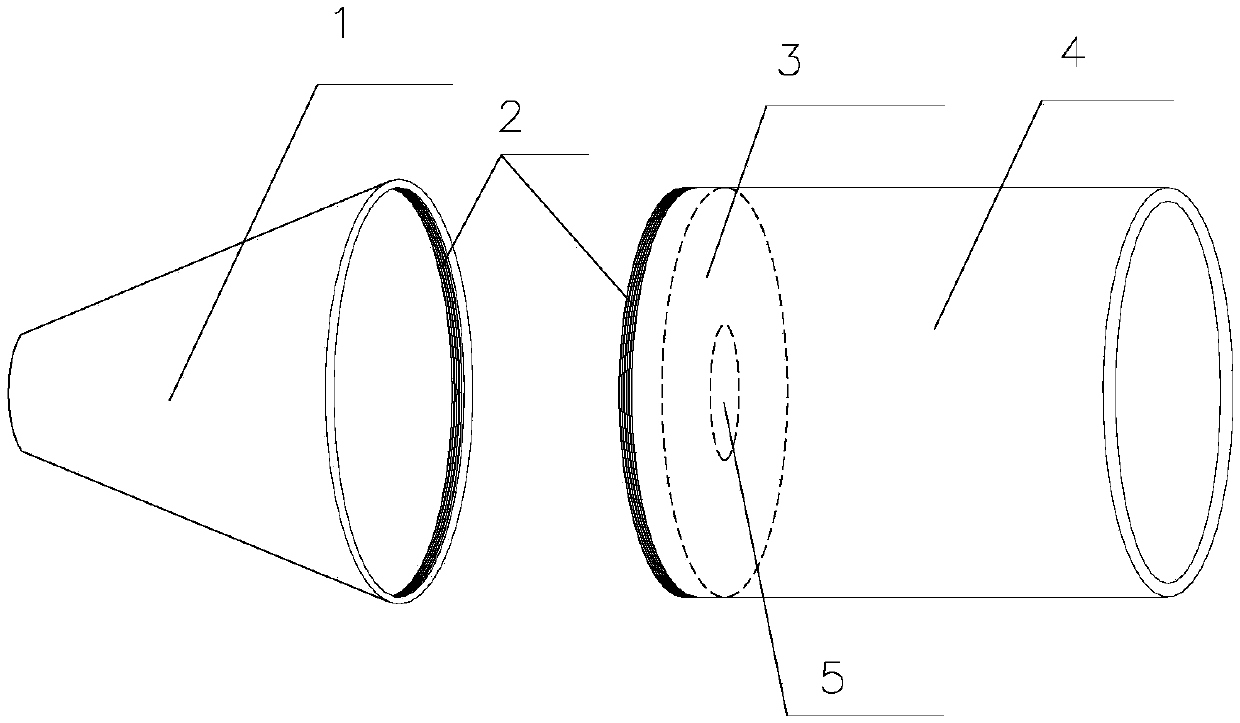
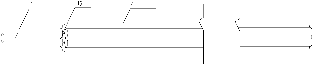
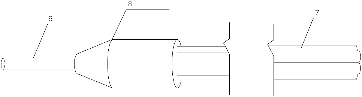
[0027] Such as figure 1 , Figure 7 As shown, a threading device for prestressed steel beams includes a steel beam probe 8 and a steel beam adjusting device 16, and the steel beam probe 8 includes a conical cylinder 1, a casing 4, and a steel beam baffle 3 , the tapered tube 1 is connected with the casing 4 by a screw, the steel bundle baffle 3 is fixed inside the casing 4, and a through hole 5 is arranged at the center of the steel bundle baffle 3; the steel bundle adjusting device 16 includes Intermediate plate 18, triangular bracket 19, brake universal wheel 17, triangular bracket 19 is fixed on the both sides of intermediate plate 18, brake universal wheel 17 is installed on the bottom of triangular bracket 19, and intermediate plate 18 is provided with different diameters. Dredge hole 20.

[0028] The tapered barrel 1 is made of stainless steel plate...


PUM


Abstract

The invention discloses a prestressed steel strand threading device and method. The device comprises a steel strand hole explorer and a steel strand adjusting device. The steel strand hole explorer comprises a conical cylinder, a protective cylinder and a steel strand baffle. The conical cylinder and the protective cylinder are connected through threads. The steel strand baffle is fixed into the protective cylinder. A through hole is formed in the center of the steel strand baffle. The steel strand adjusting device comprises a middle plate, triangular supports and brake universal wheels. The triangular supports are fixed to the two sides of the middle plate. The brake universal wheels are installed at the bottoms of the triangular supports. The middle plate is provided with dredging holes of different diameters. By adopting the design of the steel strand hole explorer and the steel strand adjusting device, threading of a steel strand can be completed through a traction device at a time, and threading of the steel strand can be rapidly and conveniently completed. The prestressed steel strand threading device has the advantages of being simple in structure, convenient and rapid to operate, efficient and the like, is suitable for being widely applied, and saves the cost due to the fact that the steel strand hole explorer and the steel strand adjusting device can be repeatedly used.

Description

technical field [0001] The invention relates to the field of bridge engineering construction, in particular to a threading device for prestressed steel beams and a threading method for prestressed steel beams. Background technique [0002] Prestress is to make up for the phenomenon of premature cracks in concrete. Before the component is used (loaded), a prestress is given to the concrete in advance, that is, in the tensile area of ​​the concrete, the steel bar is stretched by artificial force. Utilize the retraction force of the steel bar to pre-stress the tension area of ​​the concrete. This stored preload, when the component bears the tension generated by the external load, first offsets the preload in the concrete in the tension area, and then increases with the load to make the concrete tension. [0003] This limits the elongation of the concrete, delays or prevents cracks from appearing, and this is what we know as prestressed concrete. During the construction of pre...

Claims


Application Information

Patent Timeline
Patent Type & Authority Patents(China)
IPC IPC(8): E01D21/00
CPCE01D21/00
Inventor 陈强宿巳光
Owner CHINA THIRD METALLURGICAL GRP
Why Eureka
Try Eureka