Continuous stirring drilling machine

A technology of mixing drilling rig and mixing knife, which is applied in the direction of construction, sheet pile wall, foundation structure engineering, etc.

Inactive Publication Date: 2016-11-09
刘玉秋
View PDF0 Cites 0 Cited by
  • Summary
  • Abstract
  • Description
  • Claims
  • Application Information

AI Technical Summary

Problems solved by technology

[0002] At present, the walls formed by other types of cement-soil mixing drilling rigs are a combination of multiple cement-soil cylinders, not a whole cement-soil wall with the same thickness.

Method used


Image

  • Continuous stirring drilling machine
  • Continuous stirring drilling machine
  • Continuous stirring drilling machine

Examples


Embodiment Construction

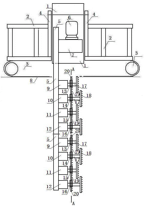
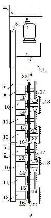
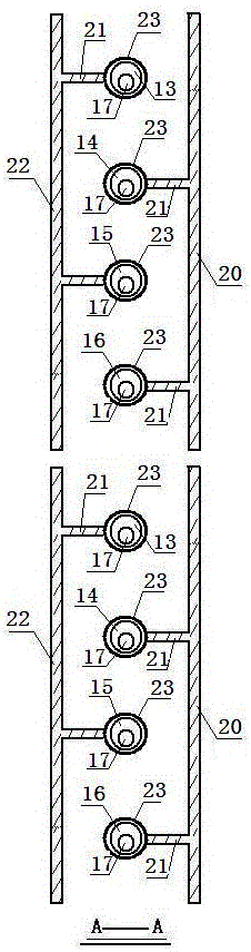
[0013] Accompanying drawing is a kind of concrete embodiment of the present invention, and this embodiment comprises the gantry main frame 2 that supports, the guide column 1 that lifts and lowers guiding use and the crawler belt walking part 3 that moves; Column, the active box 7 is fixed on the right end of the upper part of the power transmission tube, the upper part of the active box is installed with a motor 6, and the left part of the power transmission tube 5 is arranged in sequence from top to bottom. Force tube, the right end of each transfer case is respectively provided with a transfer shaft 17, and the right end of each transfer shaft is respectively provided with a cutting head 18; multiple transfer cases form a group of four from top to bottom, The first one is transfer case one 9, and transfer disc one 13 is installed eccentrically on the transfer shaft at the right end of transfer case one; the second one is transfer case two 10, and the transfer shaft at the ri...


PUM


Abstract

Disclosed is a continuous stirring drilling machine. A cement paste pouring and spraying device injects cement paste to the right end of each cutting head. The cutting heads cut and stir the soil mass and cement paste in the rotating process. In the swinging process, a plurality of first stirring blades, a plurality of second stirring blades, cutting teeth on the first stirring blades and cutting teeth on the second stirring blades cut and stir the soil mass, which is located inside a front wall and rear wall and not stirred by the cutting heads, with the cement paste. In the rightward moving process of the stirring drilling machine, continuous cement-soil walls are formed on the left side underground.

Description

technical field [0001] The invention relates to a mixing drilling machine, in particular to a continuous mixing drilling machine used in foundation anti-seepage engineering. Background technique [0002] At present, the wall formed by other types of cement-soil mixing drilling rigs is a combination of multiple cement-soil cylinders, not a whole cement-soil wall with the same thickness. Contents of the invention [0003] The present invention makes up for the above shortcomings and provides a continuous stirring drilling machine. [0004] The present invention is achieved through the following technical solutions: [0005] A continuous mixing drilling rig, including a portal main frame for support, a guide column for lifting and lowering, and a crawler walking part for moving; An electric motor is installed on the upper part of the box, and a plurality of transfer cases are arranged in sequence from top to bottom on the left part of the power transfer tube. The right end...

Claims


Application Information

Patent Timeline
Patent Type & Authority Applications(China)
IPC IPC(8): E02D5/46
CPCE02D5/46
Inventor 刘玉秋
Owner 刘玉秋
Why Eureka
Try Eureka